Toyota Corolla Cross: Replacement
REPLACEMENT
CAUTION / NOTICE / HINT
CAUTION:
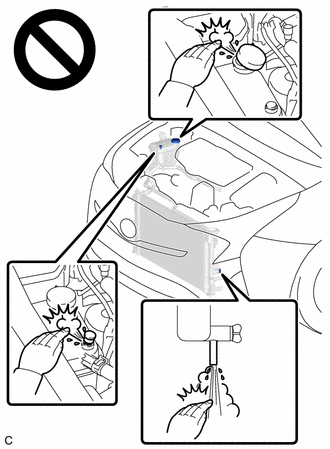
Do not remove the reserve tank cap, air release valve or radiator drain cock plug while the engine and radiator assembly are still hot. Pressurized, hot engine coolant and steam may be released and cause serious burns.

PROCEDURE
1. DRAIN ENGINE COOLANT
CAUTION:
Do not remove the reserve tank cap, air release valve or radiator drain cock plug while the engine and radiator assembly are still hot. Pressurized, hot engine coolant and steam may be released and cause serious burns.
(a) Remove the No. 1 engine under cover assembly.
Click here .gif)
.gif)
|
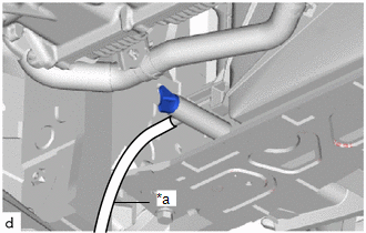
(b) Connect a hose with an inside diameter of 9 mm (0.354 in.) to the radiator drain cock as shown in the illustration. |
|
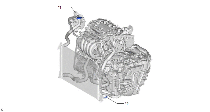
(c) Loosen the radiator drain cock plug.

|
*1 |
Reserve Tank Cap |
*2 |
Radiator Drain Cock Plug |
(d) Remove the reserve tank cap. Then drain the engine coolant.
HINT:
Collect the engine coolant in a container and dispose of it according to the regulations in your area.
(e) Tighten the radiator drain cock plug by hand.
(f) Disconnect the hose from the radiator drain cock.
(g) Install the No. 1 engine under cover assembly.
Click here .gif)
2. ADD ENGINE COOLANT
(a) Slowly fill the radiator assembly with engine coolant.
Standard Capacity:
6.7 liters (7.1 US qts, 5.9 Imp. qts)
NOTICE:
Do not substitute plain water for engine coolant.
HINT:
TOYOTA vehicles are filled with TOYOTA SLLC at the factory. In order to avoid damaging the engine cooling system and other technical problems, only use TOYOTA SLLC or similar high quality ethylene glycol based non-silicate, non-amine, non-nitrite, non-borate coolant with long-life hybrid organic acid technology (coolant with long-life hybrid organic acid technology is a combination of low phosphates and organic acids).
(b) Remove the reserve tank cap. [*1]
|
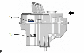
(c) Slowly pour engine coolant into the radiator reserve tank assembly until it reaches the MAX line. [*2] NOTICE: Do not substitute plain water for engine coolant. |
|
(d) Install the reserve tank cap. [*3]
(e) Install the radiator cap sub-assembly.
NOTICE:
Securely tighten the radiator cap sub-assembly.
(f) Perform the following procedure to set the engine to engine coolant filling mode. [*4]
HINT:
It is necessary to set the engine to engine coolant filling mode to ensure that a certain engine water pump assembly (water inlet housing) speed is maintained in order to circulate engine coolant.
(1) Move the shift lever to P.
(2) Start the engine.
(3) Run the engine at 1500 rpm or more for 15 seconds or more.
(4) Check that the speed of the electric water pump increases when the engine is raced to 3000 rpm.
Powertrain > Engine > Data List|
Tester Display |
|---|
|
Engine Speed |
|
Electric Water Pump Speed |
Standard:
|
Tester Display |
Condition |
Specified Condition |
|---|---|---|
|
Electric Water Pump Speed |
The engine is being raced to 3000 rpm. |
When the engine speed increases, the speed of the electric water pump also increases. |
NOTICE:
Do not move the shift lever from P, or engine coolant filling mode will be canceled.
HINT:
The speed of the engine water pump assembly (water inlet housing) changes in accordance with the engine speed when the engine is being raced in engine coolant filling mode.
(g) Bleed air from the cooling system. [*5]
NOTICE:
- Before starting the engine, turn the A/C switch off.
- Adjust the heater control to the maximum hot setting.
- Adjust the blower speed to the low setting.
(1) Warm up the engine until the thermostat opens. While the thermostat is open, circulate the engine coolant for several minutes.
HINT:
The thermostat open timing can be confirmed by squeezing the No. 2 radiator hose by hand, and sensing vibrations when the engine coolant starts to flow inside the No. 2 radiator hose.
(2) After the engine has warmed up, run the engine using the following cycle for at least 7 minutes: at 3000 rpm for 5 seconds, at idle speed for 45 seconds. (Repeat this cycle at least 8 times.)
(3) Squeeze the No. 1 radiator hose and No. 2 radiator hose several times by hand to bleed air from the system.
CAUTION:
When squeezing the No. 1 radiator hose and No. 2 radiator hose:
- Wear protective gloves.
- Be careful as the No. 1 radiator hose and No. 2 radiator hose are hot.
- Keep your hands away from the fan.
NOTICE:
- If the coolant temperature gauge indicates an excessive temperature, turn off the engine and let it cool.
- Make sure that the radiator reserve tank assembly still has some engine coolant in it.
- If the radiator reserve tank assembly does not have enough engine coolant, the engine may overheat or be seriously damaged.
- If the radiator reserve tank assembly does not have enough engine coolant, perform the following: 1) stop the engine, 2) wait until the engine coolant has cooled down, and 3) add engine coolant until the radiator reserve tank assembly is filled to the full line.
HINT:
If the flowing sound of engine coolant can still be heard after bleeding air, perform the following procedure to bleed air again.
- Warm up the engine. (With the engine idling, check that the engine coolant is flowing into the radiator reserve tank assembly.)
- Run the engine at 2000 rpm for 2 minutes or more. (A)
- Leave the engine idling for 2 minutes or more. (B)
- Repeat steps (A) and (B) 4 times or more.
(h) Wait until the engine coolant cools down. [*6]
(i) Check that the engine coolant level is between the MAX line and MIN line. [*7]
HINT:
- If the engine coolant level is below the MIN line, repeat steps from [*1] to [*7].
- If the engine coolant level is above the MAX line, drain the engine coolant until the engine coolant level is between the MAX line and MIN line.
HINT:
If the flowing sound of engine coolant can still be heard after bleeding air, perform the following procedure to bleed air again.
- Warm up the engine.
- Run the engine at 2000 rpm for 2 minutes or more. (A)
- Leave the engine idling for 2 minutes or more. (B)
- Repeat steps (A) and (B) 4 times or more.
3. INSPECT FOR COOLANT LEAK
Click here .gif)


