Toyota Corolla Cross: Leveling Motor LH Missing Message (B242487,B242587)
DESCRIPTION
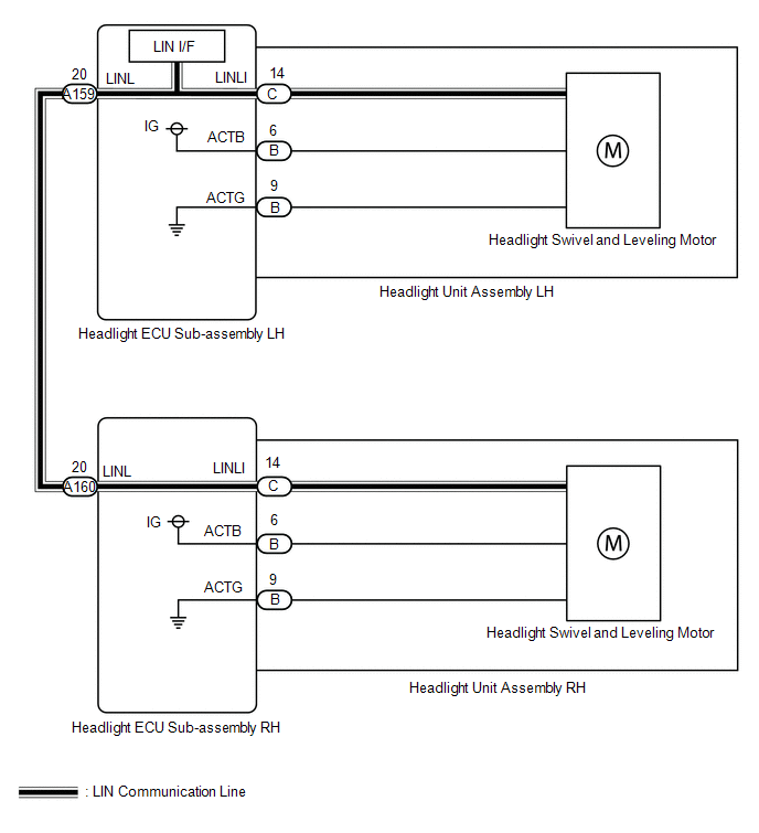
Each headlight ECU sub-assembly and headlight swivel and leveling motor communicate via LIN communication.
The headlight swivel and leveling motor operates according to power supplied and automatic headlight beam level control signals from its respective headlight ECU sub-assembly and sends its operating state to the headlight ECU sub-assembly.
|
DTC No. | Detection Item |
DTC Detection Condition | Trouble Area |
|---|---|---|---|
|
B242487 | Leveling Motor LH Missing Message | Detection condition:
|
|
| B242587 |
Leveling Motor RH Missing Message | Detection condition:
|
|
WIRING DIAGRAM
CAUTION / NOTICE / HINT
NOTICE:
If the headlight ECU sub-assembly LH has been replaced, it is necessary to synchronize the vehicle information and initialize the headlight ECU sub-assembly LH.
Click here .gif)
PROCEDURE
| 1. |
CLEAR DTC |
(a) Clear the DTCs.
Body Electrical > Headlight Control > Clear DTCs
|
.gif)
| 2. |
CHECK FOR DTC |
(a) Turn the ignition switch to ON.
(b) Wait 10 seconds or more.
(c) Check for DTCs.
Body Electrical > Headlight Control > Trouble CodesOK:
DTC B242487 and B242587 are not output.
|
Result | Proceed to |
|---|---|
|
DTCs are not output | A |
|
B242487 is output | B |
|
B242587 is output | C |
|
B242487 and B242587 are output |
D |
| A |
.gif) | USE SIMULATION METHOD TO CHECK |
| C |
| GO TO STEP 4 |
| D |
| GO TO STEP 7 |
|
| 3. |
INSPECT HEADLIGHT ECU SUB-ASSEMBLY LH |

|
*a | Component without harness connected (headlight ECU sub-assembly LH) |
- | - |
(a) Remove the headlight ECU sub-assembly LH.
Click here
(b) Measure the resistance according to the value(s) in the table below.
Standard Resistance:
|
Tester Connection | Condition |
Specified Condition |
|---|---|---|
|
A159-20 (LINL) - C-14 (LINLI) |
Always | Below 1 Ω |
| OK | | REPLACE HEADLIGHT UNIT ASSEMBLY LH
|
| NG | | REPLACE HEADLIGHT ECU SUB-ASSEMBLY LH |
| 4. |
CHECK HARNESS AND CONNECTOR (HEADLIGHT ECU SUB-ASSEMBLY LH - HEADLIGHT ECU SUB-ASSEMBLY RH) |
(a) Disconnect the A159 headlight ECU sub-assembly LH connector.
(b) Disconnect the A160 headlight ECU sub-assembly RH connector.
(c) Measure the resistance according to the value(s) in the table below.
Standard Resistance:
|
Tester Connection | Condition |
Specified Condition |
|---|---|---|
|
A159-20 (LINL) - A160-20 (LINL) |
Always | Below 1 Ω |
| NG | | REPAIR OR REPLACE HARNESS OR CONNECTOR |
|
| 5. |
CHECK HEADLIGHT ECU SUB-ASSEMBLY LH (LINL TERMINAL SIGNAL OUTPUT) |
|
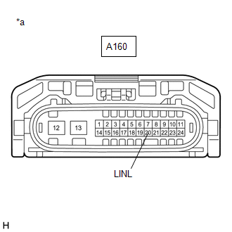
*a | Front view of wire harness connector (to Headlight ECU Sub-assembly RH) |
(a) Disconnect the headlight ECU sub-assembly RH connector.
(b) Using the GTS, check the waveform.
OK:
|
Tester Connection | Switch Condition |
Specified Condition |
|---|---|---|
|
A160-20 (LINL) - Body ground |
Ignition switch ON | Pulse generation |
| NG | | REPLACE HEADLIGHT ECU SUB-ASSEMBLY LH |
|
| 6. |
INSPECT HEADLIGHT ECU SUB-ASSEMBLY RH |
|
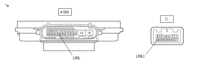
*a | Component without harness connected (Headlight ECU Sub-assembly RH) |
- | - |
(a) Remove the headlight ECU sub-assembly RH.
Click here
(b) Measure the resistance according to the value(s) in the table below.
Standard Resistance:
|
Tester Connection | Condition |
Specified Condition |
|---|---|---|
|
A160-20 (LINL) - C-14 (LINLI) |
Always | Below 1 Ω |
| OK | | REPLACE HEADLIGHT UNIT ASSEMBLY RH
|
| NG | | REPLACE HEADLIGHT ECU SUB-ASSEMBLY RH |
| 7. |
CHECK HARNESS AND CONNECTOR (HEADLIGHT ECU SUB-ASSEMBLY LH - HEADLIGHT ECU SUB-ASSEMBLY RH) |
(a) Disconnect the A159 headlight ECU sub-assembly LH connector.
(b) Disconnect the A160 headlight ECU sub-assembly RH connector.
(c) Measure the resistance according to the value(s) in the table below.
Standard Resistance:
|
Tester Connection | Condition |
Specified Condition |
|---|---|---|
|
A159-20 (LINL) - Body ground |
Always | 10 kΩ or higher |
|
A160-20 (LINL) - Body ground |
Always | 10 kΩ or higher |
| NG | | REPAIR OR REPLACE HARNESS OR CONNECTOR |
|
| 8. |
CLEAR DTC |
(a) Clear the DTCs.
Body Electrical > Headlight Control > Clear DTCs
|
| 9. |
CHECK FOR DTC |
(a) Disconnect the A160 headlight ECU sub-assembly RH connector.
(b) Turn the ignition switch to ON.
(c) Wait 10 seconds or more.
(d) Check for DTCs.
Body Electrical > Headlight Control > Trouble Codes|
Result | Proceed to |
|---|---|
|
B242587 is output | A |
|
B242487 and B242587 are output |
B |
| B |
| GO TO STEP 12 |
|
| 10. |
CLEAR DTC |
(a) Clear the DTCs.
Body Electrical > Headlight Control > Clear DTCs
|
| 11. |
CHECK FOR DTC |
(a) Remove the headlight ECU sub-assembly RH from headlight unit assembly RH.
Click here
(b) Reconnect the A160 headlight ECU sub-assembly RH connector.
(c) Turn the ignition switch to ON.
(d) Wait 10 seconds or more.
(e) Check for DTCs.
Body Electrical > Headlight Control > Trouble Codes|
Result | Proceed to |
|---|---|
|
B242587 is output | A |
|
B242487 and B242587 are output |
B |
| A |
| REPLACE HEADLIGHT UNIT ASSEMBLY RH
|
| B |
| REPLACE HEADLIGHT ECU SUB-ASSEMBLY RH |
| 12. |
CLEAR DTC |
(a) Clear the DTCs.
Body Electrical > Headlight Control > Clear DTCs
|
| 13. |
CHECK FOR DTC |
(a) Remove the headlight ECU sub-assembly LH from headlight unit assembly LH.
Click here
(b) Reconnect the A159 headlight ECU sub-assembly LH connector.
(c) Turn the ignition switch to ON.
(d) Wait 10 seconds or more.
(e) Check for DTCs.
Body Electrical > Headlight Control > Trouble Codes|
Result | Proceed to |
|---|---|
|
B242487 is output | A |
|
B242487 and B242587 are output |
B |
| A |
| REPLACE HEADLIGHT UNIT ASSEMBLY LH
|
| B |
| REPLACE HEADLIGHT ECU SUB-ASSEMBLY LH |


