Toyota Corolla Cross: ECUB Circuit Short to Ground or Open (B242F14)
DESCRIPTION
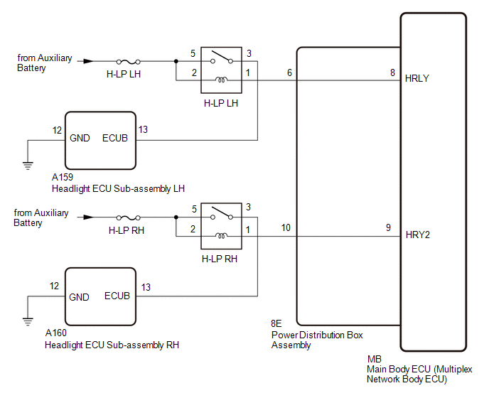
The headlight ECU sub-assembly operates using the power source voltage input from the IGR terminal and ECUB terminal.
The power source voltage of the ECUB terminal is supplied when the main body ECU (multiplex network body ECU) turns the ECUB power supply relay (H-LP LH relay and H-LP RH relay) to ON.
The headlight ECU sub-assembly compares the power source voltage supply condition of the IGR terminal and ECUB terminal and monitors the result.
|
DTC No. | Detection Item |
DTC Detection Condition | Trouble Area |
|---|---|---|---|
|
B242F14 | ECUB Circuit Short to Ground or Open | Detection condition:
|
|
|
DTC No. | Detection Item |
DTC Detection Condition | Trouble Area |
|---|---|---|---|
|
B242F14 | ECUB Circuit Short to Ground or Open | Detection condition:
|
|
WIRING DIAGRAM
CAUTION / NOTICE / HINT
NOTICE:
- Inspect the fuses for circuits related to this system before performing the following procedure.
- Before replacing the main body ECU (multiplex network body ECU), refer to Registration.
- If the headlight ECU sub-assembly LH has been replaced, it is necessary to synchronize the vehicle information and initialize the headlight ECU sub-assembly LH.
Click here
.gif)
PROCEDURE
|
1. | CLEAR DTC |
(a) Clear the DTCs.
Body Electrical > Headlight Control > Clear DTCs Body Electrical > Headlight Control (Sub) > Clear DTCs
|
.gif)
| 2. |
CHECK FOR DTC |
(a) Turn the ignition switch to ON.
(b) Wait 10 seconds or more.
(c) Check for DTCs.
Body Electrical > Headlight Control > Trouble Codes Body Electrical > Headlight Control (Sub) > Trouble CodesOK:
DTC B242F14 is not output.
|
Result | Proceed to |
|---|---|
|
OK | A |
|
NG (DTC output from headlight ECU sub-assembly LH) |
B |
| NG (DTC output from headlight ECU sub-assembly RH) |
C |
| A |
.gif) | USE SIMULATION METHOD TO CHECK |
| C |
| GO TO STEP 10 |
|
| 3. |
CHECK HARNESS AND CONNECTOR (HEADLIGHT ECU SUB-ASSEMBLY LH - BATTERY) |
|
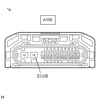
*a | Front view of wire harness connector (to Headlight ECU Sub-assembly LH) |
(a) Disconnect the headlight ECU sub-assembly LH connector.
(b) Measure the voltage according to the value(s) in the table below.
Standard Voltage:
|
Tester Connection | Switch Condition |
Specified Condition |
|---|---|---|
|
A159-13 (ECUB) - Body ground |
Ignition switch ON | 11 to 14 V |
| NG | | GO TO STEP 5 |
|
| 4. |
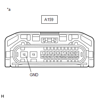
CHECK HARNESS AND CONNECTOR (HEADLIGHT ECU SUB-ASSEMBLY LH - BODY GROUND) |
(a) Disconnect the headlight ECU sub-assembly LH connector.
| (b) Measure the resistance according to the value(s) in the table below. Standard Resistance:
|
|
| OK | | REPLACE HEADLIGHT ECU SUB-ASSEMBLY LH |
| NG | | REPAIR OR REPLACE HARNESS OR CONNECTOR |
| 5. |
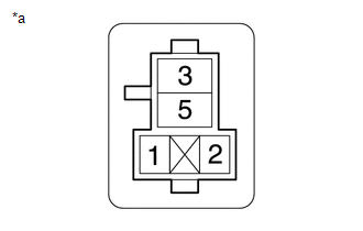
INSPECT H-LP LH RELAY |
Click here
| NG | |
REPLACE H-LP LH RELAY |
|
| 6. |
CHECK HARNESS AND CONNECTOR (H-LP LH RELAY - HEADLIGHT ECU SUB-ASSEMBLY LH) |
(a) Remove the H-LP LH relay.
(b) Disconnect the A159 headlight ECU sub-assembly LH connector.
(c) Measure the resistance according to the value(s) in the table below.
Standard Resistance:
|
Tester Connection | Condition |
Specified Condition |
|---|---|---|
|
3 (H-LP LH relay) - A159-13 (ECUB) |
Always | Below 1 Ω |
|
3 (H-LP LH relay) - Body ground |
Always | 10 kΩ or higher |
|
A159-13 (ECUB) - Body ground |
Always | 10 kΩ or higher |
| NG | | REPAIR OR REPLACE HARNESS OR CONNECTOR |
|
| 7. |
CHECK HARNESS AND CONNECTOR (H-LP LH RELAY - BATTERY) |
(a) Remove the H-LP LH relay.
| (b) Measure the voltage according to the value(s) in the table below. Standard Voltage:
|
|
| NG | | REPAIR OR REPLACE HARNESS OR CONNECTOR |
|
| 8. |
CHECK HARNESS AND CONNECTOR (H-LP LH RELAY - POWER DISTRIBUTION BOX ASSEMBLY) |
(a) Remove the H-LP LH relay.
(b) Disconnect the 8E power distribution box assembly connector.
(c) Measure the resistance according to the value(s) in the table below.
Standard Resistance:
|
Tester Connection | Condition |
Specified Condition |
|---|---|---|
|
1 (H-LP LH relay) - 8E-6 |
Always | Below 1 Ω |
|
1 (H-LP LH relay) - Body ground |
Always | 10 kΩ or higher |
|
8E-6 - Body ground | Always |
10 kΩ or higher |
| NG | | REPAIR OR REPLACE HARNESS OR CONNECTOR |
|
| 9. |
INSPECT POWER DISTRIBUTION BOX ASSEMBLY |
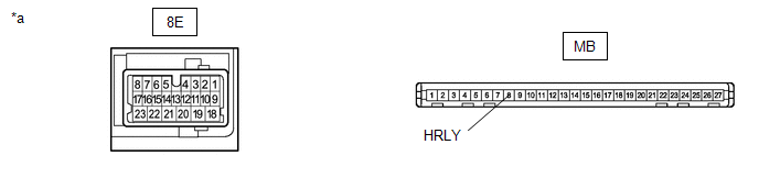
|
*a | Component without harness connected (Power Distribution Box Assembly) |
- | - |
(a) Remove the power distribution box assembly.
Click here
(b) Remove the main body ECU (multiplex network body ECU) from the power distribution box assembly.
(c) Measure the resistance according to the value(s) in the table below.
Standard Resistance:
|
Tester Connection | Condition |
Specified Condition |
|---|---|---|
|
8E-6 - MB-8 (HRLY) | Always |
Below 1 Ω |
| OK | | REPLACE MAIN BODY ECU (MULTIPLEX NETWORK BODY ECU)
|
| NG | | REPLACE POWER DISTRIBUTION BOX ASSEMBLY
|
| 10. |
CHECK HARNESS AND CONNECTOR (HEADLIGHT ECU SUB-ASSEMBLY RH - BATTERY) |
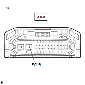
|
*a | Front view of wire harness connector (to Headlight ECU Sub-assembly RH) |
(a) Disconnect the headlight ECU sub-assembly RH connector.
(b) Measure the voltage according to the value(s) in the table below.
Standard Voltage:
|
Tester Connection | Switch Condition |
Specified Condition |
|---|---|---|
|
A160-13 (ECUB) - Body ground |
Ignition switch ON | 11 to 14 V |
| NG | | GO TO STEP 12 |
|
| 11. |
CHECK HARNESS AND CONNECTOR (HEADLIGHT ECU SUB-ASSEMBLY RH - BODY GROUND) |
(a) Disconnect the headlight ECU sub-assembly RH connector.
| (b) Measure the resistance according to the value(s) in the table below. Standard Resistance:
|
|
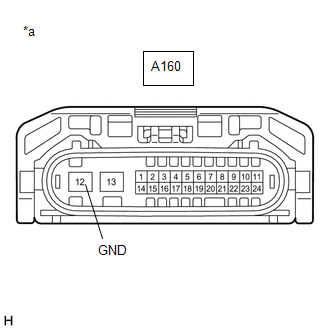
| OK | | REPLACE HEADLIGHT ECU SUB-ASSEMBLY RH |
| NG | | REPAIR OR REPLACE HARNESS OR CONNECTOR |
| 12. |
INSPECT H-LP RH RELAY |
Click here
| NG | |
REPLACE H-LP RH RELAY |
|
| 13. |
CHECK HARNESS AND CONNECTOR (H-LP RH RELAY - HEADLIGHT ECU SUB-ASSEMBLY RH) |
(a) Remove the H-LP RH relay.
(b) Disconnect the A160 headlight ECU sub-assembly RH connector.
(c) Measure the resistance according to the value(s) in the table below.
Standard Resistance:
|
Tester Connection | Condition |
Specified Condition |
|---|---|---|
|
3 (H-LP RH relay) - A160-13 (ECUB) |
Always | Below 1 Ω |
|
3 (H-LP RH relay) - Body ground |
Always | 10 kΩ or higher |
|
A160-13 (ECUB) - Body ground |
Always | 10 kΩ or higher |
| NG | | REPAIR OR REPLACE HARNESS OR CONNECTOR |
|
| 14. |
CHECK HARNESS AND CONNECTOR (H-LP RH RELAY - BATTERY) |
(a) Remove the H-LP RH relay.
| (b) Measure the voltage according to the value(s) in the table below. Standard Voltage:
|
|
| NG | | REPAIR OR REPLACE HARNESS OR CONNECTOR |
|
| 15. |
CHECK HARNESS AND CONNECTOR (H-LP RH RELAY - POWER DISTRIBUTION BOX ASSEMBLY) |
(a) Remove the H-LP RH relay.
(b) Disconnect the 4E power distribution box assembly connector.
(c) Measure the resistance according to the value(s) in the table below.
Standard Resistance:
|
Tester Connection | Condition |
Specified Condition |
|---|---|---|
|
1 (H-LP RH relay) - 4E-10 |
Always | Below 1 Ω |
|
1 (H-LP RH relay) - Body ground |
Always | 10 kΩ or higher |
|
4E-10 - Body ground | Always |
10 kΩ or higher |
| NG | | REPAIR OR REPLACE HARNESS OR CONNECTOR |
|
| 16. |
INSPECT POWER DISTRIBUTION BOX ASSEMBLY |
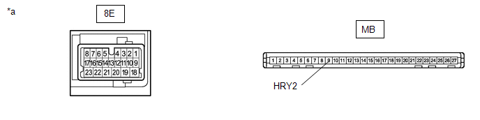
|
*a | Component without harness connected (Power Distribution Box Assembly) |
- | - |
(a) Remove the power distribution box assembly.
Click here
(b) Remove the main body ECU (multiplex network body ECU) from the power distribution box assembly.
(c) Measure the resistance according to the value(s) in the table below.
Standard Resistance:
|
Tester Connection | Condition |
Specified Condition |
|---|---|---|
|
8E-10 - MB-9 (HRLY2) |
Always | Below 1 Ω |
| OK | | REPLACE MAIN BODY ECU (MULTIPLEX NETWORK BODY ECU)
|
| NG | | REPLACE POWER DISTRIBUTION BOX ASSEMBLY
|


