Toyota Corolla Cross: Key Reminder Buzzer does not Sound
DESCRIPTION
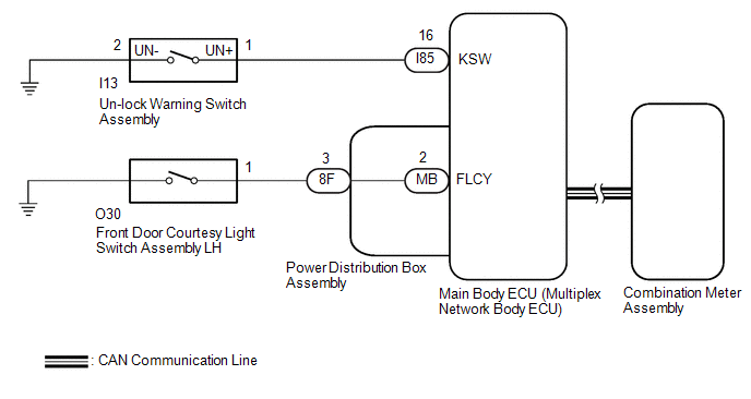
The key reminder warning buzzer sounds when the driver door is opened while the ignition switch is off or ACC. The key reminder warning buzzer is activated when the main body ECU (multiplex network body ECU) sends an un-lock warning switch signal and driver door courtesy light switch signal to the combination meter assembly via CAN communication.
WIRING DIAGRAM
CAUTION / NOTICE / HINT
NOTICE:
The key reminder warning system uses the CAN communication system. Inspect the communication function by following How to Proceed with Troubleshooting. Troubleshoot the key reminder warning system after confirming that the communication systems are functioning properly.
Click here .gif)
PROCEDURE
| 1. |
PERFORM ACTIVE TEST USING GTS (BUZZER OPERATION) |
(a) Perform the Active Test according to the display on the GTS.
Body Electrical > Combination Meter > Active Test|
Tester Display | Measurement Item |
Control Range | Diagnostic Note |
|---|---|---|---|
|
Buzzer Operation (800Hz, Vol L, W/ Damping) |
Combination meter buzzer
| ON |
- |
|
Tester Display |
|---|
| Buzzer Operation (800Hz, Vol L, W/ Damping) |
|
Result | Proceed to |
|---|---|
|
Combination meter buzzer sounds |
A |
| Combination meter buzzer does not sound |
B |
| B |
.gif) | REPLACE COMBINATION METER ASSEMBLY
|
|
.gif)
| 2. |
READ VALUE USING GTS (FL DOOR COURTESY SW STATUS) |
(a) Read the Data List according to the display on the GTS.
Body Electrical > Main Body > Data List|
Tester Display | Measurement Item |
Range | Normal Condition |
Diagnostic Note |
|---|---|---|---|---|
|
FL Door Courtesy Switch Status |
Front door courtesy light switch assembly LH signal |
Close or Open | Close: Front door LH closed Open: Front door LH open |
- |
|
Tester Display |
|---|
| FL Door Courtesy Switch Status |
OK:
The GTS indicates ON or OFF according to the driver door conditions shown in the table.
| NG | | GO TO LIGHTING SYSTEM
|
|
| 3. |
READ VALUE USING GTS (KEY UNLOCK WARNING SW) |
(a) Read the Data List according to the display on the GTS.
Body Electrical > Main Body > Data List|
Tester Display | Measurement Item |
Range | Normal Condition |
Diagnostic Note |
|---|---|---|---|---|
|
Key Unlock Warning Switch |
Un-lock warning switch signal |
OFF or ON | OFF: Ignition key not inserted ON: Ignition key inserted |
- |
|
Tester Display |
|---|
| Key Unlock Warning Switch |
OK:
The GTS indicates ON or OFF according to whether the key is in the ignition key cylinder.
| OK | | REPLACE MAIN BODY ECU (MULTIPLEX NETWORK BODY ECU)
|
|
| 4. |
INSPECT UN-LOCK WARNING SWITCH ASSEMBLY |
Click here
| NG | | REPLACE UN-LOCK WARNING SWITCH ASSEMBLY |
|
| 5. |
CHECK HARNESS AND CONNECTOR (UN-LOCK WARNING SWITCH ASSEMBLY - MAIN BODY ECU (MULTIPLEX NETWORK BODY ECU) AND BODY GROUND) |
(a) Disconnect the I85 main body ECU (multiplex network body ECU) connector.
(b) Measure the resistance according to the value(s) in the table below.
Standard Resistance:
|
Tester Connection | Condition |
Specified Condition |
|---|---|---|
|
I85-16 (KSW) - I13-1 (UN+) |
Always | Below 1 Ω |
|
I13-2 (UN-) - Body ground |
Always | Below 1 Ω |
|
I85-16 (KSW) or I13-1 (UN+) - Other terminals and body ground |
Always | 10 kΩ or higher |
| OK | | REPLACE MAIN BODY ECU (MULTIPLEX NETWORK BODY ECU)
|
| NG | | REPAIR OR REPLACE HARNESS OR CONNECTOR |


