Toyota Corolla Cross: Intermediate Shaft Speed Sensor "C" Circuit Short to Battery (P274912,P274914,P274931)
DESCRIPTION
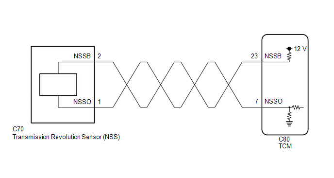
The transmission revolution sensor (NSS) detects the secondary pulley speed and sends it to the TCM.
The TCM determines the current gear ratio from the transmission revolution sensor (NSS) signal.
|
DTC No. |
Detection Item |
DTC Detection Condition |
Trouble Area |
MIL |
Memory |
Note |
|---|---|---|---|---|---|---|
|
P274912 |
Intermediate Shaft Speed Sensor "C" Circuit Short to Battery |
The transmission revolution sensor (NSS) signal is normal but the transmission revolution sensor (NSS) output voltage is higher than 1.8 V for 4.5 seconds or more (1-trip detection logic). |
|
Comes on |
DTC stored |
SAE Code: P07CA |
|
P274914 |
Intermediate Shaft Speed Sensor "C" Circuit Short to Ground or Open |
The transmission revolution sensor (NSS) signal is normal but the transmission revolution sensor (NSS) output voltage is less than 0.2 V for 4.5 seconds or more (1-trip detection logic). |
|
Comes on |
DTC stored |
SAE Code: P07C9 |
|
P274931 |
Intermediate Shaft Speed Sensor "C" No Signal |
When the transmission revolution sensor (NOUT) signal indicates 350 rpm or more and the transmission revolution sensor (NT) signal indicates 780 rpm or more, the transmission revolution sensor (NSS) signal indicates less than 300 rpm for 5 seconds or more (1-trip detection logic). |
|
Comes on |
DTC stored |
SAE Code: P2751 |
MONITOR DESCRIPTION
The TCM receives signals from the transmission revolution sensor (NSS) installed to the continuously variable transaxle and determines the secondary pulley speed in order to control the gear ratio.
If the TCM detects no signal from the transmission revolution sensor (NSS) even while the vehicle is being driven, it will determine that in the transmission revolution sensor (NSS) is malfunctioning, illuminate the MIL and store a DTC.
MONITOR STRATEGY
|
Related DTCs |
P07C9: Intermediate shaft speed sensor (for Belt Drive) (Transmission revolution sensor (NSS))/Range check (Low voltage) P07CA: Intermediate shaft speed sensor (for Belt Drive) (Transmission revolution sensor (NSS))/Range check (High voltage) P2751: Intermediate shaft speed sensor (for Belt Drive) (Transmission revolution sensor (NSS))/Verify pulse input |
|
Required sensors/Components |
Transmission revolution sensor (NSS) Transmission revolution sensor (NT) Transmission revolution sensor (NOUT) |
|
Frequency of operation |
Continuous |
|
Duration |
P07C9, P07CA: 4.5 sec. P2751: 5 sec. |
|
MIL operation |
Immediate |
|
Sequence of operation |
None |
TYPICAL ENABLING CONDITIONS
All|
Auxiliary battery voltage |
8 V or more |
|
Ignition switch |
ON |
|
Starter |
OFF |
|
Intermediate shaft speed sensor pulse input fail (P2751) (Pending / MIL) |
Not detected |
|
Intermediate shaft speed sensor range check fail (P07C9, P07CA) (Pending / MIL) |
Not detected |
|
D range position switch |
ON |
|
R range position switch |
OFF |
|
Park position switch |
OFF |
|
Neutral position switch |
OFF |
|
Engine |
Running |
|
Pressure control solenoid circuit fail (P08CA, P08CB, P0962, P0963, P0966, P0967, P2826, P2827, P282F, P2830) (Pending + MIL) |
Not detected |
|
Torque converter clutch pressure control solenoid circuit fail (P2763, P2764) (Pending + MIL) |
Not detected |
|
Output speed sensor revolution |
350 rpm or more |
|
Turbine speed sensor revolution |
780 rpm or more |
- Condition (A)
Condition (B)ECT
20°C (68°F) or more
ECT sensor circuit fail (P0117, P0118)
(Pending + MIL)
Not detected
All of the following conditions are met
2 sec. or more
- Park position switch
OFF
- Neutral position switch
OFF
One of the following conditions is met
-
- ECT
Less than 20°C (68°F)
- ECT sensor circuit fail (P0117, P0118)
(Pending + MIL)
Detected
All of the following conditions are met
30 sec. or more
- Park position switch
OFF
- Neutral position switch
OFF
TYPICAL MALFUNCTION THRESHOLDS
P2751|
Intermediate shaft speed sensor revolution |
Less than 300 rpm |
|
Intermediate shaft speed sensor voltage |
Less than 0.2 V |
|
Intermediate shaft speed sensor voltage |
More than 1.8 V |
COMPONENT OPERATING RANGE
P2751|
Intermediate shaft speed sensor revolution |
300 rpm or more |
|
Intermediate shaft speed sensor voltage |
0.2 V or more and 1.8 V or less |
CONFIRMATION DRIVING PATTERN
CAUTION:
When performing the confirmation driving pattern, obey all speed limits and traffic laws.
HINT:
- After repairs have been completed, clear the DTCs and then check that the vehicle has returned to normal by performing the following All Readiness check procedure.
- When clearing the permanent DTCs, refer to the Clear Permanent DTC procedure.
Click here
.gif)
- Clear the DTCs (even if no DTCs are stored, perform the clear DTC procedure).
- Turn the ignition switch off and wait for 2 minutes or more.
- Turn the ignition switch to ON and turn the GTS on.
- Start the engine.
- Perform the D Position Shift Test inspection in Road Test. [*1]
Click here
HINT:
[*1]: Normal judgment procedure.
The normal judgment procedure is used to complete DTC judgment and also used when clearing permanent DTCs.
- Stop the vehicle.
- Enter the following menus: Powertrain / Transmission / Utility / All Readiness.
- Input the DTC: P274912, P274914 or P274931.
- Check the DTC judgment result.
GTS Display
Description
NORMAL
- DTC judgment completed
- System normal
ABNORMAL
- DTC judgment completed
- System abnormal
INCOMPLETE
- DTC judgment not completed
- Perform driving pattern after confirming DTC enabling conditions
N/A
- Unable to perform DTC judgment
- Number of DTCs which do not fulfill DTC preconditions has reached ECU memory limit
HINT:
- If the judgment result shows NORMAL, the system is normal.
- If the judgment result shows ABNORMAL, the system has a malfunction.
- If the judgment result shows INCOMPLETE or N/A, perform the normal judgment procedure again.
WIRING DIAGRAM
CAUTION / NOTICE / HINT
CAUTION:
- Strictly observe posted speed, limits, traffic laws and road conditions.
.png)
- Do not drive the vehicle with the cable of the GTS contacting the pedals, shift lever or steering wheel.
- Driving the vehicle with the cable of the GTS contacting these areas could impede vehicle control, resulting in a serious accident.
- Do not operate the GTS while driving the vehicle.
.png)
- Operating the GTS while driving the vehicle will prevent you from paying sufficient attention to vehicle surroundings, and could result in a serious accident.
NOTICE:
- Perform the universal trip to clear permanent DTCs.
Click here
- Perform registration and/or initialization when parts related to the continuously
variable transaxle system are replaced.
Click here
- Check that no DTCs are stored after performing initialization.
Click here
PROCEDURE
|
1. |
READ VALUE USING GTS (NSS SENSOR SPEED AND NSS SENSOR VOLTAGE) |
(a) Enter the following menus:
(b) According to the display on the GTS, read the Data List.
Powertrain > Transmission > Data List|
Tester Display |
Measurement Item |
Range |
Normal Condition |
Diagnostic Note |
|---|---|---|---|---|
|
NSS Sensor Speed |
Secondary pulley speed (NSS) |
Min.: 0 rpm Max.: 65535 rpm |
|
- |
|
NSS Sensor Voltage |
Transmission revolution sensor (NSS) output voltage |
Min.: 0.000 V Max.: 4.999 V |
0.2 to 1.8 V: Engine idling (Vehicle stopped with shift lever in P or N) |
- |
|
Tester Display |
|---|
|
NSS Sensor Speed |
|
NSS Sensor Voltage |
|
Result |
Proceed to |
|---|---|
|
Data List values are normal |
A |
|
Data List values are not normal |
B |
| B | .gif) |
GO TO STEP 3 |
|
.gif)
|
2. |
REPLACE TCM |
Click here
| NEXT | |
PERFORM REGISTRATION AND INITIALIZATION for Registration: Click here for Initialization: Click here |
|
3. |
INSPECT TRANSMISSION REVOLUTION (NSS) SENSOR |
Click here
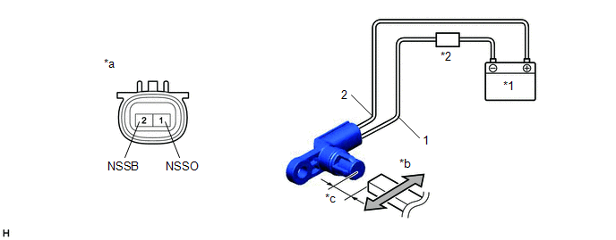
(a) Connect the auxiliary battery to the transmission revolution sensor (NSS) as shown in the illustration.
|
*1 |
Auxiliary battery |
*2 |
Ammeter |
|
*a |
Component without harness connected (Transmission Revolution Sensor (NSS)) |
*b |
Magnet |
|
*c |
5 mm or less |
- |
- |
(b) Wave a magnet left and right 5 mm (0.197 in.) or less from the tip of the transmission revolution sensor (NSS) to output a high/low signal while measuring the current.
NOTICE:
Make sure to wave the magnet during the inspection. The current will not change unless the magnet is moved as shown in the illustration.
(c) Measure the current according to the value(s) in the table below.
Standard Current:
|
Tester Connection |
Condition |
Specified Condition |
|---|---|---|
|
1 (NSSO) - 2 (NSSB) |
Low signal |
4 to 8 mA |
|
1 (NSSO) - 2 (NSSB) |
High signal |
12 to 16 mA |
| NG | |
REPLACE TRANSMISSION REVOLUTION (NSS) SENSOR
|
|
|
4. |
CHECK HARNESS AND CONNECTOR (TRANSMISSION REVOLUTION SENSOR (NSS) - TCM) |
(a) Disconnect the C70 transmission revolution sensor (NSS) connector.
(b) Disconnect the C80 TCM connector.
(c) Measure the resistance according to the value(s) in the table below.
Standard Resistance:
|
Tester Connection |
Condition |
Specified Condition |
|---|---|---|
|
C70-1 (NSSO) - C80-7 (NSSO) |
Always |
Below 1 Ω |
|
C70-2 (NSSB) - C80-23 (NSSB) |
Always |
Below 1 Ω |
|
C70-1 (NSSO) or C80-7 (NSSO) - Body ground and other terminals |
Always |
10 kΩ or higher |
|
C70-2 (NSSB) or C80-23 (NSSB) - Body ground and other terminals |
Always |
10 kΩ or higher |
(d) Connect the C80 TCM connector.
(e) Connect the C70 transmission revolution sensor (NSS) connector.
| NG | |
REPAIR OR REPLACE HARNESS OR CONNECTOR (TRANSMISSION REVOLUTION SENSOR (NSS) - TCM) |
|
|
5. |
REPLACE TCM |
Click here
| NEXT | |
PERFORM REGISTRATION AND INITIALIZATION for Registration: Click here for Initialization: Click here |
READ NEXT:
 Torque Converter Clutch Pressure Control Solenoid Control Circuit Performance/Stuck
Off (P275600,P27567E)
Torque Converter Clutch Pressure Control Solenoid Control Circuit Performance/Stuck
Off (P275600,P27567E)
DESCRIPTION
Using the current from the TCM, the shift solenoid valve SLU controls the lock-up
clutch pressure, and performs lock-up and flex lock-up control.
The TCM compares the engagement condit
Torque Converter Clutch Pressure Control Solenoid Control Circuit Short to Battery
(P275612)
DESCRIPTION
Using the current from the TCM, the shift solenoid valve SLU controls the lock-up
clutch pressure, and performs lock-up and flex lock-up control.
DTC No.
Detectio
Torque Converter Clutch Pressure Control Solenoid Control Circuit Short to Ground
or Open (P275614)
DESCRIPTION
Refer to DTC P275612.
Click here
DTC No.
Detection Item
DTC Detection Condition
Trouble Area
MIL
Memory
No
SEE MORE:
 Removal
REMOVAL
CAUTION / NOTICE / HINT
COMPONENTS (REMOVAL)
Procedure
Part Name Code
1
FRONT DOOR OPENING TRIM WEATHERSTRIP
62312B
-
-
-
2
FRONT PILLAR GA
Passenger Seat Occupant Classification Sensor "A" Component Internal Failure (B00C096)
DESCRIPTION
DTC No. Detection Item
DTC Detection Condition Trouble Area
Warning Indicate Test Mode / Check Mode
B00C096 Passenger Seat Occupant Classification Sensor "A" Component Internal Failure
Front occupant classification sensor LH malfunction
Front o
