Toyota Corolla Cross: Installation
INSTALLATION
CAUTION / NOTICE / HINT
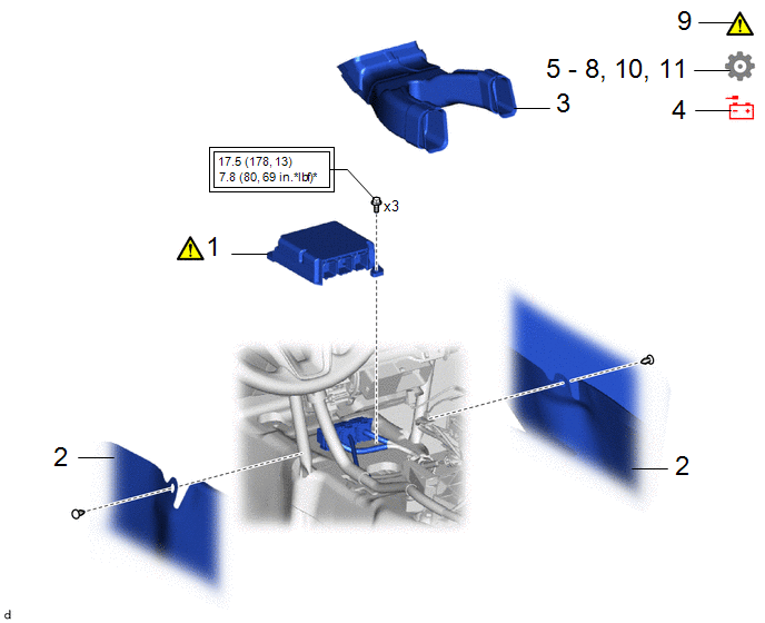
COMPONENTS (INSTALLATION)
|
Procedure | Part Name Code |
.png) |
.png) |
 |
|---|---|---|---|---|---|
|
1 | AIRBAG ECU ASSEMBLY |
89170A |
|
- | - |
|
2 | FRONT FLOOR CARPET ASSEMBLY |
58510D | - |
- | - |
|
3 | NO.1 CONSOLE BOX DUCT |
58861B | - |
- | - |
|
4 | CABLE TO NEGATIVE AUXILIARY BATTERY TERMINAL |
- | - |
- | - |
|
5 | WRITE VIN/VEHICLE IDENTIFICATION NUMBER |
- | - |
- |
|
|
6 | ECU CONFIGURATION |
- | - |
- |
|
|
7 | UPDATE ECU SECURITY KEY |
- | - |
- |
|
|
8 | SWITCHING SPECIFICATION INFORMATION |
- | - |
- |
|
|
9 | INSPECT SRS WARNING LIGHT |
|
- | - |
- |
| 10 |
INITIALIZATION AFTER RECONNECTING AUXILIARY BATTERY TERMINAL |
- | - |
- |
|
|
11 | SYSTEM INITIALIZATION |
- | - |
- |
|
.png) |
Tightening torque for "Major areas involving basic vehicle performance such as moving/turning/stopping": N*m (kgf*cm, ft.*lbf) |
* | For use with a union nut wrench |
CAUTION / NOTICE / HINT
NOTICE:
- After replacing the airbag ECU assembly, make sure to perform Write VIN/Vehicle Identification Number, ECU Configuration, Update ECU Security Key, and Switching Specification Information.
- After performing the update ECU security key procedure, make sure to perform the initialization procedure for when the cable has been disconnected and reconnected to the negative (-) auxiliary battery terminal.
PROCEDURE
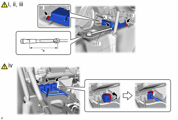
1. INSTALL AIRBAG ECU ASSEMBLY
.png)
|
*A | w/ Smart Key System |
*B | w/o Smart Key System |
|
*a | Illumination off |
- | - |
(1) Check that the ignition switch is off.
(2) Check that the cable is disconnected from the negative (-) auxiliary battery terminal.
CAUTION:
- Wait at least 90 seconds after disconnecting the cable from the negative (-) auxiliary battery terminal to disable the SRS system.
- If the airbag deploys for any reason, it may cause a serious accident.

|
*a | Torque Wrench Fulcrum Length |
- | - |
.png) |
Push in | - |
- |
(1) Install the airbag ECU assembly with the 2 bolts (B).
Torque:
17.5 N·m {178 kgf·cm, 13 ft·lbf}
NOTICE:
- If the airbag ECU assembly has been dropped, or there are any cracks, dents or other defects in the case or connector, replace it with a new one.
- When installing the airbag ECU assembly, make sure that the SRS wiring does not interfere with or is not pinched between other parts.
- When the ignition switch is first turned to on (IG) after the airbag ECU assembly has been replaced, make sure that no one is in the vehicle.
(2) Using SST, install the bolt (A).
SST: 09729-00120
Torque:
Specified tightening torque :
17.5 N·m {178 kgf·cm, 13 ft·lbf}
HINT:
- Calculate the torque wrench reading when changing the fulcrum length of the torque wrench.
Click here
.gif)
- When using SST (fulcrum length of 200 mm (7.87 in.)) + torque wrench (fulcrum length of 162 mm (6.38 in.)):
7.8 N*m (80 kgf*cm, 69 in.*lbf)
(3) Check that there is no looseness in the installed parts of the airbag ECU assembly.
(4) Connect the 3 connectors and push in the lock lever to lock the connector.
NOTICE:
When connecting any airbag connector, take care not to damage the airbag wire harness.
2. INSTALL FRONT FLOOR CARPET ASSEMBLY
3. INSTALL NO. 1 CONSOLE BOX DUCT
4. CONNECT CABLE TO NEGATIVE AUXILIARY BATTERY TERMINAL
- for Gasoline Model
Click here
.gif)
- for HEV Model
Click here
.gif)
5. WRITE VIN/VEHICLE IDENTIFICATION NUMBER
Click here
.gif)
6. ECU CONFIGURATION
Click here
.gif)
7. UPDATE ECU SECURITY KEY
Click here
.gif)
8. SWITCHING SPECIFICATION INFORMATION
Click here .gif)
9. INSPECT SRS WARNING LIGHT
.png) |
Click here |
10. INITIALIZATION AFTER RECONNECTING AUXILIARY BATTERY TERMINAL
HINT:
When disconnecting and reconnecting the auxiliary battery, there is an automatic learning function that completes learning when the respective system is used.
Click here .gif)
11. PERFORM SYSTEM INITIALIZE
- for HEV Model:
Click here
.gif)
- for Gasoline Model:
Click here
.gif)


