Toyota Corolla Cross: Installation
INSTALLATION
CAUTION / NOTICE / HINT
COMPONENTS (INSTALLATION)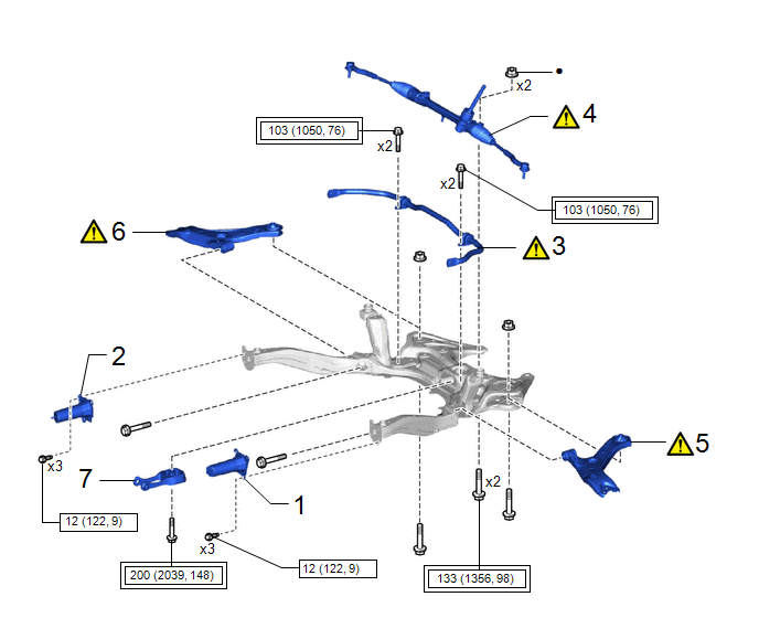
|
Procedure |
Part Name Code |
.png) |
.png) |
.png) |
|
|---|---|---|---|---|---|
|
1 |
FRONT BUMPER BAR REINFORCEMENT LH |
52134C |
- |
- |
- |
|
2 |
FRONT BUMPER BAR REINFORCEMENT RH |
52133C |
- |
- |
- |
|
3 |
FRONT STABILIZER BAR |
48811 |
|
- |
- |
|
4 |
STEERING LINK ASSEMBLY |
- |
|
- |
- |
|
5 |
TEMPORARILY INSTALL FRONT LOWER NO. 1 SUSPENSION ARM SUB-ASSEMBLY LH |
48069 |
|
- |
- |
|
6 |
TEMPORARILY INSTALL FRONT LOWER NO. 1 SUSPENSION ARM SUB-ASSEMBLY RH |
48068 |
|
- |
- |
|
7 |
INSTALL ENGINE MOVING CONTROL ROD |
12363A |
- |
- |
- |
.png) |
Tightening torque for "Major areas involving basic vehicle performance such as moving/turning/stopping" : N*m (kgf*cm, ft.*lbf) |
● |
Non-reusable part |
|
Procedure |
Part Name Code |
|
|
|
|
|---|---|---|---|---|---|
|
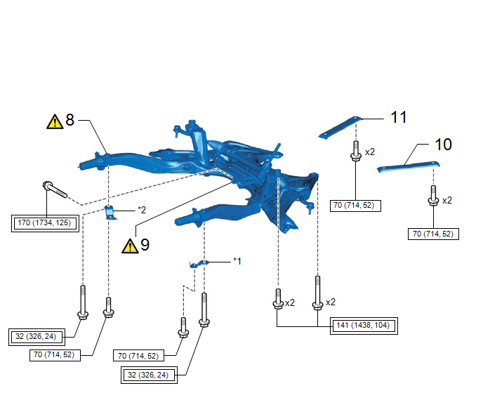
8 |
FRONT SUSPENSION CROSSMEMBER SUB-ASSEMBLY |
51201F |
|
- |
- |
|
9 |
CONNECT ENGINE MOVING CONTROL ROD |
12363A |
|
- |
- |
|
10 |
NO. 2 CROSSMEMBER GUSSET LH |
51322 |
- |
- |
- |
|
11 |
NO. 2 CROSSMEMBER GUSSET RH |
51321 |
- |
- |
- |
|
*1 |
CENTER RADIATOR SUPPORT LH |
*2 |
CENTER RADIATOR SUPPORT RH |
|
|
Tightening torque for "Major areas involving basic vehicle performance such as moving/turning/stopping" : N*m (kgf*cm, ft.*lbf) |
.png) |
N*m (kgf*cm, ft.*lbf): Specified torque |
|
Procedure |
Part Name Code |
|
|
|
|
|---|---|---|---|---|---|
|
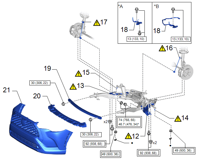
12 |
CONNECT FRONT LOWER NO. 1 SUSPENSION ARM SUB-ASSEMBLY LH |
48069 |
|
- |
- |
|
13 |
CONNECT FRONT LOWER NO. 1 SUSPENSION ARM SUB-ASSEMBLY RH |
48068 |
|
- |
- |
|
14 |
TIE ROD END SUB-ASSEMBLY LH |
45047 |
|
- |
- |
|
15 |
TIE ROD END SUB-ASSEMBLY RH |
45046 |
|
- |
- |
|
16 |
FRONT STABILIZER LINK ASSEMBLY LH |
48810 |
|
- |
- |
|
17 |
FRONT STABILIZER LINK ASSEMBLY RH |
48820B |
|
- |
- |
|
18 |
WIRING HARNESS CLAMP BRACKET |
82715W |
- |
- |
- |
|
19 |
FRONT NO. 2 BUMPER REINFORCEMENT |
52132A |
- |
- |
- |
|
20 |
LOWER FRONT BUMPER ABSORBER |
52618 |
- |
- |
- |
|
21 |
FRONT BUMPER ASSEMBLY |
- |
- |
- |
- |
|
*A |
except Gasoline Model AWD |
*B |
for Gasoline Model AWD |
|
|
Tightening torque for "Major areas involving basic vehicle performance such as moving/turning/stopping" : N*m (kgf*cm, ft.*lbf) |
* |
For use with a ball joint lock nut wrench |
|
● |
Non-reusable part |
- |
- |
|
Procedure |
Part Name Code |
|
|
|
|
|---|---|---|---|---|---|
|
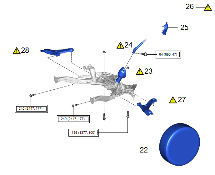
22 |
FRONT WHEELS |
- |
- |
- |
- |
|
23 |
NO. 1 STEERING COLUMN HOLE COVER SUB-ASSEMBLY |
45025D |
- |
- |
- |
|
24 |
NO. 2 STEERING INTERMEDIATE SHAFT ASSEMBLY |
45260 |
|
- |
- |
|
25 |
COLUMN HOLE COVER SILENCER SHEET |
45259A |
- |
- |
- |
|
26 |
STABILIZE SUSPENSION |
- |
|
- |
- |
|
27 |
FULLY TIGHTEN FRONT LOWER NO. 1 SUSPENSION ARM SUB-ASSEMBLY LH |
48069 |
|
- |
- |
|
28 |
FULLY TIGHTEN FRONT LOWER NO. 1 SUSPENSION ARM SUB-ASSEMBLY RH |
48068 |
|
- |
- |
|
|
Tightening torque for "Major areas involving basic vehicle performance such as moving/turning/stopping" : N*m (kgf*cm, ft.*lbf) |
- |
- |
|
Procedure |
Part Name Code |
|
|
|
|
|---|---|---|---|---|---|
|
29 |
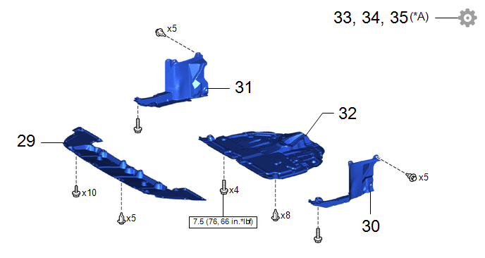
CENTER ENGINE UNDER COVER |
51451A |
- |
- |
- |
|
30 |
ENGINE UNDER COVER REAR LH |
51444A |
- |
- |
- |
|
31 |
ENGINE UNDER COVER REAR RH |
51443C |
- |
- |
- |
|
32 |
NO. 1 ENGINE UNDER COVER ASSEMBLY |
51410 |
- |
- |
- |
|
33 |
INSPECT AND ADJUST FRONT WHEEL ALIGNMENT |
- |
- |
- |
|
|
34 |
PERFORM END POSITION INITIAL SETTING |
- |
- |
- |
|
|
35 |
PERFORM INITIALIZATION |
- |
- |
- |
|
|
*A |
w/ Parking Assist Monitor System |
- |
- |
|
|
N*m (kgf*cm, ft.*lbf): Specified torque |
- |
- |
PROCEDURE
1. INSTALL FRONT BUMPER BAR REINFORCEMENT LH
- for Sport Package:
Click here
.gif)
- except Sport Package:
Click here
2. INSTALL FRONT BUMPER BAR REINFORCEMENT RH
3. INSTALL FRONT STABILIZER BAR
|
|
Click here |
4. INSTALL STEERING LINK ASSEMBLY
|
|
Click here |
5. TEMPORARILY INSTALL FRONT LOWER NO. 1 SUSPENSION ARM SUB-ASSEMBLY LH
|
|
NOTICE: Because the nut has its own stopper, do not turn the nut. Tighten the bolt with the nut secured. |
6. TEMPORARILY INSTALL FRONT LOWER NO. 1 SUSPENSION ARM SUB-ASSEMBLY RH
7. INSTALL ENGINE MOVING CONTROL ROD
Torque:
200 N·m {2039 kgf·cm, 148 ft·lbf}
8. INSTALL FRONT SUSPENSION CROSSMEMBER SUB-ASSEMBLY
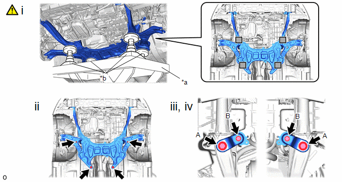
|
*a |
Engine Lifter |
*b |
Attachment |
 |
Attachment placement location |
- |
- |
(1) Slowly jack up the front suspension crossmember sub-assembly with an engine lifter using 4 attachments or equivalent tools.
CAUTION:
- The front suspension crossmember sub-assembly is a very heavy component. Make sure that it is supported securely.
- If the front suspension crossmember sub-assembly is not securely supported, it may drop, resulting in serious injury.
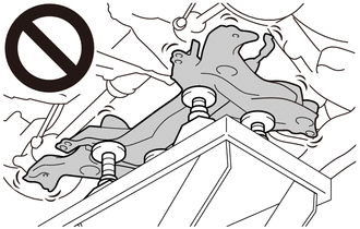
NOTICE:
- Use attachments to keep the front suspension crossmember sub-assembly level.
- Make sure that the front suspension crossmember sub-assembly not hit the protrusion of the reinforcement.
- After installation, check that the claws of the steering column hole cover
base are not disengaged.
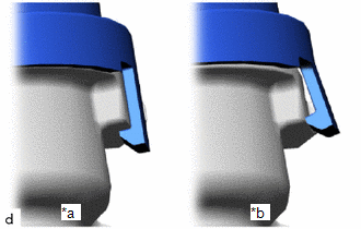
*a
Correct
*b
Incorrect
(2) Install the front suspension crossmember sub-assembly to the vehicle body with the 4 bolts.
Torque:
141 N·m {1438 kgf·cm, 104 ft·lbf}
(3) Install radiator support CTR LH with the 2 bolts.
Torque:
Bolt (A) :
32 N·m {326 kgf·cm, 24 ft·lbf}
Bolt (B) :
70 N·m {714 kgf·cm, 52 ft·lbf}
(4) Install radiator support CTR RH with the 2 bolts.
Torque:
Bolt (A) :
32 N·m {326 kgf·cm, 24 ft·lbf}
Bolt (B) :
70 N·m {714 kgf·cm, 52 ft·lbf}
9. CONNECT ENGINE MOVING CONTROL ROD
Torque:
170 N·m {1734 kgf·cm, 125 ft·lbf}
10. INSTALL NO. 2 CROSSMEMBER GUSSET LH
Torque:
70 N·m {714 kgf·cm, 52 ft·lbf}
11. INSTALL NO. 2 CROSSMEMBER GUSSET RH
12. CONNECT FRONT LOWER NO. 1 SUSPENSION ARM SUB-ASSEMBLY LH
|
|
Click here |
13. CONNECT FRONT LOWER NO. 1 SUSPENSION ARM SUB-ASSEMBLY RH
14. CONNECT TIE ROD END SUB-ASSEMBLY LH

(1) Connect the tie rod end sub-assembly LH to the steering knuckle LH with the nut.
Torque:
49 N·m {500 kgf·cm, 36 ft·lbf}
NOTICE:
- Do not damage the ball joint dust cover.
- Further tighten the nut up to 60° if the holes for the cotter pin are not aligned.
(2) Install a new cotter pin.
15. CONNECT TIE ROD END SUB-ASSEMBLY RH
16. CONNECT FRONT STABILIZER LINK ASSEMBLY LH
|
|
NOTICE: Do not damage the boot of the ball joint. |

|
*a |
Torque Wrench Fulcrum Length |
*b |
Ball Joint Lock Nut Wrench |
(1) Using a ball joint lock nut wrench, install the front stabilizer link assembly LH to the front stabilizer bar with the nut.
Torque:
Specified tightening torque :
74 N·m {755 kgf·cm, 55 ft·lbf}
HINT:
- Calculate the torque wrench reading when changing the fulcrum length of
the torque wrench.
Click here
- When using a ball joint lock nut wrench (fulcrum length of 149 mm (5.87
in.)) + torque wrench. (fulcrum length of 255 mm (10.04 in.)):
46.7 N*m (476 kgf*cm, 34 ft.*lbf)
(2) If the ball joint turns together with the nut, use a 6 mm hexagon socket wrench to hold the stud bolt.
17. CONNECT FRONT STABILIZER LINK ASSEMBLY RH
18. INSTALL WIRING HARNESS CLAMP BRACKET
Torque:
13 N·m {133 kgf·cm, 10 ft·lbf}
19. INSTALL NO.2 FRONT BUMPER REINFORCEMENT
- for Sport Package:
Click here
- except Sport Package:
Click here
20. INSTALL FRONT BUMPER LOWER ABSORBER
21. INSTALL FRONT BUMPER ASSEMBLY
- for Sport Package:
Click here
- except Sport Package:
Click here
22. INSTALL FRONT WHEELS
Click here
23. INSTALL NO. 1 STEERING COLUMN HOLE COVER SUB-ASSEMBLY
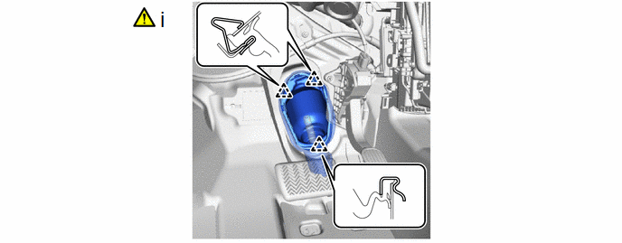
(1) Connect the No. 1 steering column hole cover sub-assembly by the below procedure.
1. Engage the clip (B) to the vehicle body.
2. Engage the clip (A) to install the No. 1 steering column hole cover sub-assembly to the vehicle body.
NOTICE:
- Be careful not to damage the lip of the No. 1 steering column hole cover sub-assembly.
- Check that the No. 1 steering column hole cover sub-assembly is securely installed.
- Check that the No. 1 steering column hole cover sub-assembly and vehicle body are in close contact with one another.
24. CONNECT NO. 2 STEERING INTERMEDIATE SHAFT ASSEMBLY
|
|
Click here |
25. INSTALL COLUMN HOLE COVER SILENCER SHEET
26. STABILIZE SUSPENSION
|
|
Click here |
27. FULLY TIGHTEN FRONT LOWER NO. 1 SUSPENSION ARM SUB-ASSEMBLY LH
|
|
Click here |
28. FULLY TIGHTEN FRONT LOWER NO. 1 SUSPENSION ARM SUB-ASSEMBLY RH
29. INSTALL CENTER ENGINE UNDER COVER
30. INSTALL ENGINE UNDER COVER REAR LH
31. INSTALL ENGINE UNDER COVER REAR RH
32. INSTALL NO. 1 ENGINE UNDER COVER ASSEMBLY
Click here
33. INSPECT AND ADJUST FRONT WHEEL ALIGNMENT
Click here
34. PERFORM END POSITION INITIAL SETTING
Click here
35. PERFORM INITIALIZATION (w/ Parking Assist Monitor System)
|
Parking assist monitor system |
|
|
Automatic headlight beam level control system |
|


