Toyota Corolla Cross: Installation
INSTALLATION
CAUTION / NOTICE / HINT
COMPONENTS (INSTALLATION)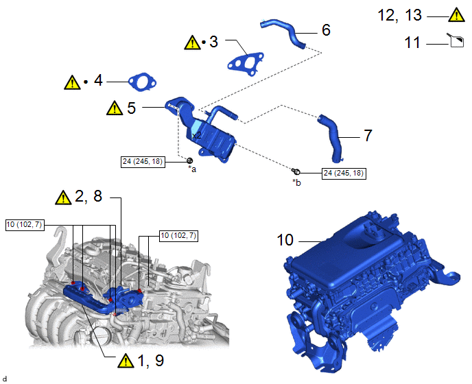
|
Procedure | Part Name Code |
.png) |
.png) |
 |
|---|---|---|---|---|---|
|
1 | LOOSEN NO. 1 EGR PIPE SUB-ASSEMBLY |
25601 |
|
- | - |
|
2 | LOOSEN EGR VALVE ASSEMBLY |
25620 |
|
- | - |
|
3 | NO. 1 EGR COOLER GASKET |
25685 |
|
- | - |
|
4 | EGR VALVE GASKET |
25627 |
|
- | - |
|
5 | EGR COOLER ASSEMBLY |
25680 |
|
- | - |
|
6 | NO. 4 WATER BY-PASS HOSE |
16281 | - |
- | - |
|
7 | NO. 3 WATER BY-PASS HOSE |
16267 | - |
- | - |
|
8 | TIGHTEN EGR VALVE ASSEMBLY |
25620 |
|
- | - |
|
9 | TIGHTEN NO. 1 EGR PIPE SUB-ASSEMBLY |
25601 |
|
- | - |
|
10 | INVERTER WITH CONVERTER ASSEMBLY |
G92A0 | - |
- | - |
|
11 | ADD ENGINE COOLANT |
- | - |
|
- |
| 12 |
INSPECT FOR COOLANT LEAK |
- |
|
- | - |
|
13 | INSPECT FOR EXHAUST GAS LEAK |
- |
|
- | - |
|
*a | x2 or x3 |
*b | x3 or x2 |
.png) |
N*m (kgf*cm, ft.*lbf): Specified torque |
- | - |
|
● | Non-reusable part |
- | - |
CAUTION / NOTICE / HINT
NOTICE:
This procedure includes the installation of small-head bolts. Refer to Small-Head Bolts of Basic Repair Hint to identify the small-head bolts.
Click here .gif)
PROCEDURE
1. LOOSEN NO. 1 EGR PIPE SUB-ASSEMBLY
.png)
(1) Using an 8 mm socket wrench, loosen the 4 bolts of the No. 1 EGR pipe sub-assembly.
NOTICE:
- As the bolts of the No. 1 EGR pipe sub-assembly are only to be loosened, it is not necessary to replace the EGR inlet gasket and EGR valve adapter gasket.
- If the No. 1 EGR pipe sub-assembly is removed, it is necessary to replace the EGR inlet gasket and EGR valve adapter gasket with new ones.
2. LOOSEN EGR VALVE ASSEMBLY
.png)
(1) Using an 8 mm socket wrench, loosen the 2 bolts EGR valve assembly.
3. INSTALL NO. 1 EGR COOLER GASKET
.png)
|
*a | Claw |
- | - |
(1) Install a new No. 1 EGR cooler gasket to the EGR cooler assembly.
NOTICE:
Make sure that the claws of the No. 1 EGR cooler gasket are toward the EGR cooler assembly side.
4. INSTALL EGR VALVE GASKET
.png)
|
*a | Claw |
- | - |
(1) Install a new EGR valve gasket to the EGR cooler assembly.
NOTICE:
Make sure that the claws of the EGR valve gasket are toward the EGR cooler assembly side.
5. INSTALL EGR COOLER ASSEMBLY
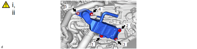
[The illustrations are representative examples, and details may differ.]
(1) Temporarily install the EGR cooler assembly to the cylinder head sub-assembly and EGR valve assembly with the bolts and nuts.
(2) Tighten the bolts and nuts in the order shown in the illustration.
Torque:
24 N·m {245 kgf·cm, 18 ft·lbf}
6. CONNECT NO. 4 WATER BY-PASS HOSE
7. CONNECT NO. 3 WATER BY-PASS HOSE
8. TIGHTEN EGR VALVE ASSEMBLY
.png)
(1) Using an 8 mm socket wrench, tighten the 2 bolts of the EGR valve assembly.
Torque:
10 N·m {102 kgf·cm, 7 ft·lbf}
9. TIGHTEN NO. 1 EGR PIPE SUB-ASSEMBLY
.png)
(1) Using an 8 mm socket wrench, tighten the 4 bolts of the No. 1 EGR pipe sub-assembly.
Torque:
10 N·m {102 kgf·cm, 7 ft·lbf}
10. INSTALL INVERTER WITH CONVERTER ASSEMBLY
Click here
11. ADD ENGINE COOLANT (for Engine)
Click here
12. INSPECT FOR COOLANT LEAK (for Engine)
Click here
13. INSPECT FOR EXHAUST GAS LEAK
Click here


