Toyota Corolla Cross: Generator Position Sensor Internal Electronic Failure (P1CAC49,P1C641F,P1CAF38)
DESCRIPTION
The motor generator control ECU (MG ECU), which is built into the inverter with converter assembly, monitors its internal operation and detects malfunctions.
|
DTC No. | Detection Item |
DTC Detection Condition |
Trouble Area | MIL |
Warning Indicate | Note |
|---|---|---|---|---|---|---|
|
P1C641F | Generator Control Module Circuit Intermittent |
Excitation signal (REF signal) for resolver angle detection cycle malfunction detected when DTC P0C7917, P0E5717, P0D3319, P1C5D19, P1C5F19 or P1C5E19 is stored. (1 trip detection logic) |
| Does not come on |
Master Warning: Does not come on |
SAE Code: P1C64 |
|
P1CAC49 | Generator Position Sensor Internal Electronic Failure |
Generator resolver angle malfunction: The difference between the resolver angle for control and estimated resolver angle exceeds the allowable limit. (1 trip detection logic) |
| Comes on |
Master Warning: Comes on |
SAE Code: P1CAC |
|
P1CAF38 | Generator Position Sensor REF Signal Cycle Malfunction Signal Frequency Incorrect |
Resolver REF signal cycle malfunction: Excitation signal (REF signal) for resolver angle detection cycle malfunction (1 trip detection logic) |
| Comes on |
Master Warning: Comes on |
SAE Code: P1CAF |
MONITOR DESCRIPTION
The motor generator control ECU performs diagnostic tests to verify proper operation of internal ECU systems. In this diagnostic monitor, the motor generator control ECU checks for an R/D (Resolver/Digital Converter) malfunction involving the generator resolver. If motor generator control ECU detects an R/D error, it will conclude that there is an internal malfunction involving the generator resolver. The motor generator control ECU will illuminate the MIL and store a DTC.
MONITOR STRATEGY
|
Related DTCs | P1CAC (INF P1CAC49): Generator Control Module R/D Processing (Generator Position) Performance P1CAF (INF P1CAF38): Generator Position Sensor Reference Signal Performance |
|
Required sensors/components | Generator resolver |
|
Frequency of operation | Continuous |
|
Duration | TMC's intellectual property |
|
MIL operation | Immediately |
|
Sequence of operation | None |
TYPICAL ENABLING CONDITIONS
|
The monitor will run whenever the following DTCs are not stored |
TMC's intellectual property |
|
Other conditions belong to TMC's intellectual property |
- |
TYPICAL MALFUNCTION THRESHOLDS
|
TMC's intellectual property |
- |
COMPONENT OPERATING RANGE
|
Motor generator control ECU | DTC P1CAC (INF P1CAC49) is not detected DTC P1CAF (INF P1CAF38) is not detected |
CONFIRMATION DRIVING PATTERN
HINT:
- After repair has been completed, clear the DTC and then check that the vehicle has returned to normal by performing the following All Readiness check procedure.
Click here
.gif)
- When clearing the permanent DTCs, refer to the "CLEAR PERMANENT DTC" procedure.
Click here
- Clear the DTCs (even if no DTCs are stored, perform the clear DTC procedure).
- Turn the ignition switch off and wait for 2 minutes or more.
- Turn the ignition switch to ON and wait for 5 seconds or more.* [*1]
*: Lightly wiggle the connectors and wire harnesses up and down and right and left.
- Turn the ignition switch to ON (READY) and wait for 5 seconds or more. [*2]
- Depress the accelerator pedal of the vehicle with the engine stopped and shift lever in P to start the engine. [*3]
- Keep the engine running for 5 seconds or more. [*4]
- Drive the vehicle forward with the shift lever in D for 5 m (16 ft.) or more. [*5]
- Drive the vehicle backward with the shift lever in R for 5 m (16 ft.) or more. [*6]
HINT:
[*1] to [*6]: Normal judgment procedure.
The normal judgment procedure is used to complete DTC judgment and also used when clearing permanent DTCs.
- Enter the following menus: Powertrain / Motor Generator / Utility / All Readiness.
- Check the DTC judgment result.
HINT:
- If the judgment result shows NORMAL, the system is normal.
- If the judgment result shows ABNORMAL, the system has a malfunction.
- If the judgment result shows INCOMPLETE, perform the normal judgment procedure again.
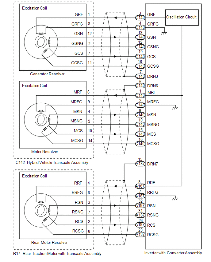
WIRING DIAGRAM
CAUTION / NOTICE / HINT
CAUTION:
Refer to the precautions before inspecting high voltage circuit.
Click here
NOTICE:
- After the ignition switch is turned off, there may be a waiting time before disconnecting the negative (-) auxiliary battery terminal.
Click here
- When disconnecting and reconnecting the auxiliary battery.
HINT:
When disconnecting and reconnecting the auxiliary battery, there is an automatic learning function that completes learning when the respective system is used.
Click here
HINT:
- If the problem symptom cannot be reproduced, performing a road test on a road on which the vehicle tends to vibrate will make it easier to reproduce the symptom.
- If the resolver is malfunctioning, the vehicle may not drive smoothly.
- When inspecting the connectors, if it is difficult to judge if a connector was disconnected, deformed or improperly secured, disconnect and reconnect the connector and then check for DTCs again. Check if the same DTC is output. If the same DTC is not output, improper connection of connectors is suspected.
- As a malfunction detection threshold may be exceeded when performing the vibration or heat connector inspections, make sure to perform the following inspection to check that the DTC was not stored due to the malfunction of a part.
- P1CAC49, P1C641F and P1CAF38 may be output as a result of the malfunction indicated by the DTCs in table below.
- The chart above is listed in inspection order of priority.
- Check DTCs that are output at the same time by following the listed order. (The main cause of the malfunction can be determined without performing unnecessary inspections.)
|
System | Relevant DTC | |
|---|---|---|
|
Motor generator control system | P0A3F16 |
Drive Motor "A" Position Sensor Circuit Voltage Below Threshold |
|
P0A4516 | Drive Motor B" Position Sensor Circuit Voltage Below Threshold | |
|
P0A4B16 | Generator Position Sensor Circuit Voltage Below Threshold | |
|
P0C6413 | Generator Position Sensor Circuit "A" Circuit Open | |
|
P0C6416 | Generator Position Sensor Circuit "A" Circuit Voltage Below Threshold | |
|
P0C6417 | Generator Position Sensor Circuit "A" Circuit Voltage Above Threshold | |
|
P0C6913 | Generator Position Sensor Circuit "B" Circuit Open | |
|
P0C6916 | Generator Position Sensor Circuit "B" Circuit Voltage Below Threshold | |
|
P0C6917 | Generator Position Sensor Circuit "B" Circuit Voltage Above Threshold | |
PROCEDURE
|
1. | CHECK CONNECTOR CONNECTION CONDITION (INVERTER WITH CONVERTER ASSEMBLY CONNECTOR) |
Click here
|
Result | Proceed to |
|---|---|
|
OK | A |
|
NG (The connector is not connected securely.) |
B |
| NG (The terminals are not making secure contact or are deformed, or water or foreign matter exists in the connector.) |
C |
| B | .gif) | CONNECT SECURELY |
| C | | REPAIR OR REPLACE HARNESS OR CONNECTOR |
|
.gif)
|
2. | CHECK GENERATOR RESOLVER CIRCUIT |
Click here
|
|
3. | CHECK MOTOR RESOLVER CIRCUIT |
Click here
|
|
4. | CHECK REAR MOTOR RESOLVER CIRCUIT |
Click here
HINT:
If the "Rear Motor Resolver Circuit" inspection results are normal, perform the next step.
| NEXT | | REPLACE INVERTER WITH CONVERTER ASSEMBLY |


