Toyota Corolla Cross: Installation
INSTALLATION
CAUTION / NOTICE / HINT
COMPONENTS (INSTALLATION)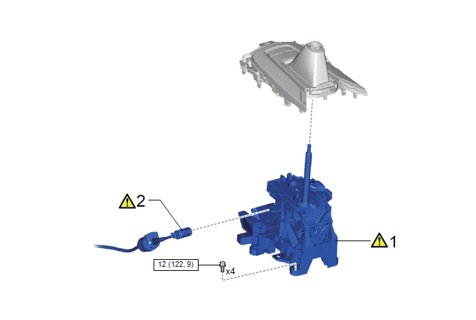
|
Procedure |
Part Name Code |
.png) |
.png) |
.png) |
|
|---|---|---|---|---|---|
|
1 |
TRANSMISSION FLOOR SHIFT ASSEMBLY |
- |
|
- |
- |
|
2 |
TRANSMISSION CONTROL CABLE ASSEMBLY |
33820B |
|
- |
- |
.png) |
N*m (kgf*cm, ft.*lbf): Specified torque |
- |
- |
|
Procedure |
Part Name Code |
|
|
|
|
|---|---|---|---|---|---|
|
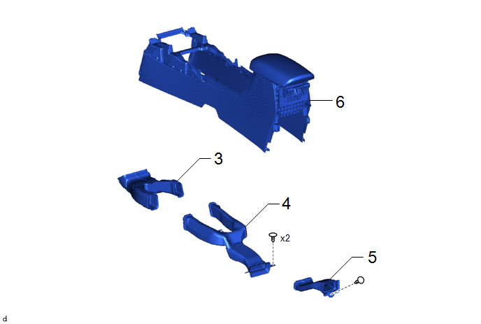
3 |
NO. 1 CONSOLE BOX DUCT |
58861B |
- |
- |
- |
|
4 |
NO. 2 CONSOLE BOX DUCT |
58862B |
- |
- |
- |
|
5 |
NO. 3 CONSOLE BOX DUCT |
58863A |
- |
- |
- |
|
6 |
CONSOLE BOX ASSEMBLY |
58810J |
- |
- |
- |
|
Procedure |
Part Name Code |
|
|
|
|
|---|---|---|---|---|---|
|
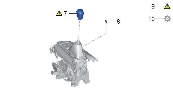
7 |
SHIFT LEVER KNOB SUB-ASSEMBLY |
33504F |
|
- |
- |
|
8 |
SHIFT LOCK RELEASE BUTTON COVER |
33554C |
- |
- |
- |
|
9 |
INSPECT SHIFT LEVER POSITION |
- |
|
- |
- |
|
10 |
ADJUST SHIFT LEVER POSITION |
- |
- |
- |
|
PROCEDURE
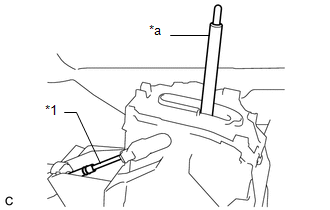
1. INSTALL TRANSMISSION FLOOR SHIFT ASSEMBLY
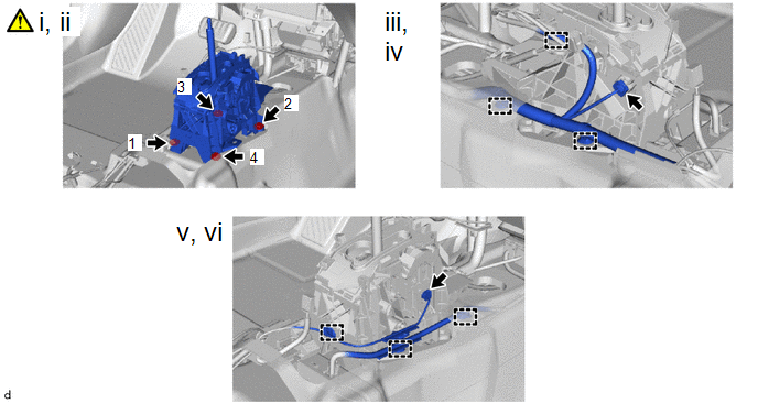
(1) Temporarily install the transmission floor shift assembly to the vehicle body with the 4 bolts.
(2) Fully tighten the 4 bolts in the order shown in the illustration.
Torque:
12 N·m {122 kgf·cm, 9 ft·lbf}
(3) Engage the 3 clamps to install the wire harness.
(4) Connect the connector.
(5) Engage the 3 clamps to install the wire harness.
(6) Connect the connector.
2. CONNECT TRANSMISSION CONTROL CABLE ASSEMBLY
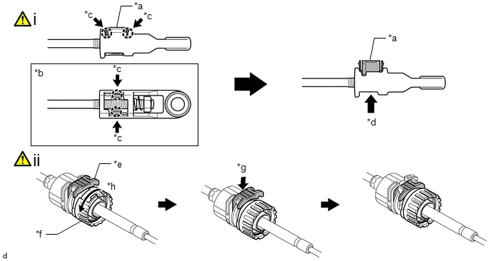
|
*a |
Lock Piece |
*b |
Bottom View |
|
*c |
Push |
*d |
Push up |
|
*e |
Stopper |
*f |
Nut |
|
*g |
Push in |
*h |
Turn approximately 180° |
(1) Push the 2 claws together at the top of the lock piece. While holding the 2 claws together, push the 2 lugs on the bottom of the lock piece toward each other and upward to push up the lock piece.
(2) Turn the nut of the transmission control cable assembly approximately 180° counterclockwise. While holding the nut in place, push in the stopper until it clicks twice.
HINT:
- If the stopper cannot be pushed in, slightly turn the nut clockwise and then push in the stopper again.
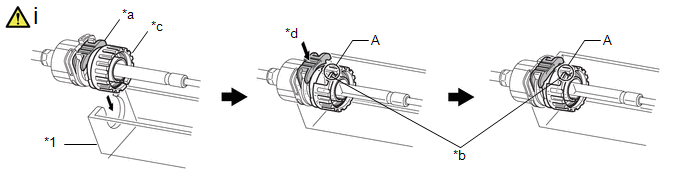
|
*1 |
Transmission Floor Shift Assembly |
- |
- |
|
*a |
Stopper |
*b |
Spring |
|
*c |
Nut |
*d |
Push in |
(1) Connect the transmission control cable assembly to the transmission floor shift assembly. Check that the spring is positioned at (A) and push in the stopper.
NOTICE:
- If the stopper cannot be pushed in, slightly turn the nut clockwise and then push in the stopper again.
- Make sure that the transmission control cable assembly is securely locked.
- Do not forcibly pull the transmission control cable assembly into the cabin.
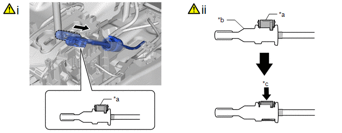
|
*a |
Lock Piece |
*b |
Adjuster Case |
|
*c |
Push in |
- |
- |
(1) Confirm that the shift lever is in N, and then install the end of the transmission control cable assembly to the transmission floor shift assembly.
NOTICE:
- Securely install the end of the transmission control cable assembly to the transmission floor shift assembly.
- Install the end of the transmission control cable assembly so that its adjustment lock section is on the driver side.
(2) Push the lock piece into the adjuster case.
NOTICE:
- Check that the park/neutral position switch assembly and shift lever are in N.
- Securely push in the lock piece until the 2 claws are engaged.
- When pushing in the lock piece of the adjuster case to lock it, remove your
hand from the lever shaft.
*1
Transmission Control Cable Assembly
*a
Lever Shaft
- When pushing in the lock piece of the adjuster case to lock it, do not move the lever shaft or transmission control cable assembly forward or backward.
3. INSTALL NO. 1 CONSOLE BOX DUCT
4. INSTALL NO. 2 CONSOLE BOX DUCT
5. INSTALL NO. 3 CONSOLE BOX DUCT
6. INSTALL CONSOLE BOX ASSEMBLY
Click here .gif)
7. INSTALL SHIFT LEVER KNOB SUB-ASSEMBLY
|
|
Click here |
8. INSTALL SHIFT LOCK RELEASE BUTTON COVER
9. INSPECT SHIFT LEVER POSITION
Click here
10. ADJUST SHIFT LEVER POSITION
Click here


