Toyota Corolla Cross Owners & Service Manuals

Toyota Corolla Cross: On-vehicle Inspection

ON-VEHICLE INSPECTION

PROCEDURE

1. INSPECT AUTOMATIC LIGHT CONTROL SENSOR

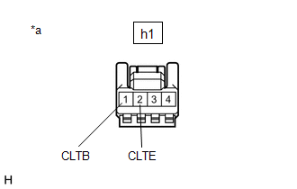
(a) Disconnect the h1 automatic light control sensor connector.

(b) Measure the voltage and resistance according to the value(s) in the table below.

Standard Voltage:

Tester Connection

Condition

Specified Condition

h1-1 (CLTB) - h1-2 (CLTE)

Ignition switch off

Below 1 V

h1-1 (CLTB) - h1-2 (CLTE)

Ignition switch ON

11 to 14 V

Standard Resistance:

Tester Connection

Condition

Specified Condition

h1-2 (CLTE) - Body ground

Always

Below 1 Ω

If the result is not as specified, there may be a malfunction on the wire harness side.

*a

Front view of wire harness connector

(Automatic Light Control Sensor)

(c) Connect the h1 automatic light control sensor connector.

(d) Connect an oscilloscope to terminals h1-2 (CLTE) and h1-4 (CLTS) of the automatic light control sensor connector and check the waveform.
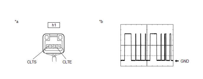
*a

Component with harness connected

(Automatic Light Control Sensor)

*b

Waveform

OK:

Tester Connection

Condition

Tool Setting

Specified Condition

h1-2 (CLTE) - h1-4 (CLTS)

Ignition switch ON

2 V/DIV., 10 ms./DIV.

Pulse generation

(See waveform)

HINT:

The communication waveform changes according to the surrounding brightness.

If the result is not as specified, the automatic light control sensor may be malfunctioning.

    READ NEXT:

     Removal

    REMOVAL CAUTION / NOTICE / HINT COMPONENTS (REMOVAL) Procedure Part Name Code 1 INSTRUMENT PANEL SAFETY PAD ASSEMBLY - - - - 2 AUTOMATI

     Installation

    INSTALLATION CAUTION / NOTICE / HINT COMPONENTS (INSTALLATION) Procedure Part Name Code 1 AUTOMATIC LIGHT CONTROL SENSOR 89120A - - - 2

     Interior Panels / Trim

    SEE MORE:

     Hybrid/EV Battery Energy Control Module Hybrid/EV Battery Monitor Performance (P0E2D00)

    DESCRIPTION The battery ECU assembly detects the voltage of each HV battery cell. The battery ECU assembly monitors its internal HV battery cell voltage detection circuits to detect malfunctions. If the battery ECU assembly detects a malfunction it will store this DTC. HINT: If this DTC is output

     Inspection

    INSPECTION PROCEDURE 1. INSPECT DOOR CONTROL TRANSMITTER SUB-ASSEMBLY (a) Inspect operation of the door control transmitter sub-assembly. (1) Remove the transmitter battery from the door control transmitter sub-assembly. Click here (2) Install a new or non-depleted transmitter battery.

    © 2020-2024 Copyright www.tcorollacross.com