Toyota Corolla Cross: Installation
INSTALLATION
CAUTION / NOTICE / HINT
COMPONENTS (INSTALLATION)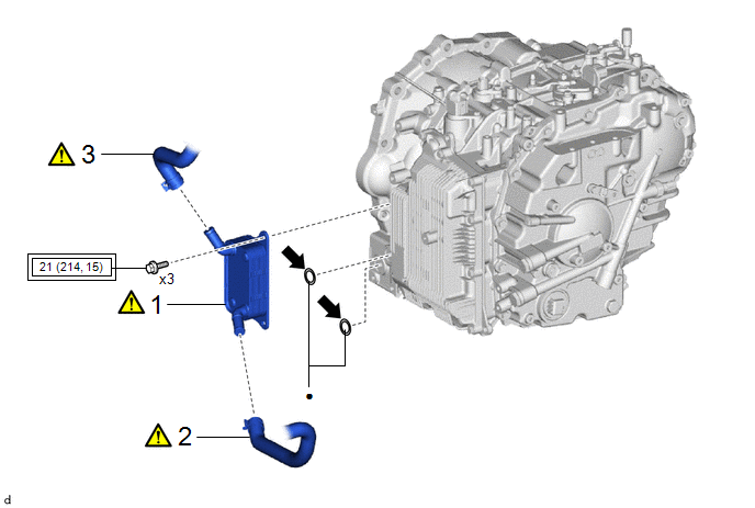
|
Procedure |
Part Name Code |
.png) |
.png) |
.png) |
|
|---|---|---|---|---|---|
|
1 |
TRANSMISSION OIL COOLER |
33493C |
|
- |
- |
|
2 |
NO. 2 WATER BY-PASS HOSE |
16264D |
|
- |
- |
|
3 |
INLET WATER HOSE |
16262 |
|
- |
- |
.png) |
Tightening torque for "Major areas involving basic vehicle performance such as moving/turning/stopping": N*m (kgf*cm, ft.*lbf) |
● |
Non-reusable part |
.png) |
Toyota Genuine CVT Fluid FE |
- |
- |
 -
-
|
Procedure |
Part Name Code |
|
|
|
|
|---|---|---|---|---|---|
|
4 |
ADD ENGINE COOLANT |
- |
- |
|
- |
|
5 |
ADJUST CONTINUOUSLY VARIABLE TRANSAXLE FLUID |
- |
- |
|
- |
|
6 |
INSPECT FOR COOLANT LEAK |
- |
|
- |
- |
|
7 |
INSPECT FOR CONTINUOUSLY VARIABLE TRANSAXLE FLUID LEAK |
- |
|
- |
- |
|
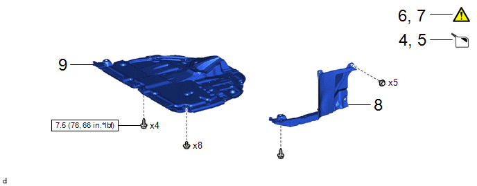
8 |
REAR ENGINE UNDER COVER LH |
51444A |
- |
- |
- |
|
9 |
NO. 1 ENGINE UNDER COVER ASSEMBLY |
51410 |
- |
- |
- |
.png) |
N*m (kgf*cm, ft.*lbf): Specified torque |
- |
- |
PROCEDURE
1. INSTALL TRANSMISSION OIL COOLER
|
|
Toyota Genuine CVT fluid FE |
- |
- |
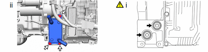
(1) Coat 2 new O-rings with Toyota Genuine CVT fluid FE and install them to the transaxle housing.
NOTICE:
Ensure that the O-rings are not twisted.
(2) Install the transmission oil cooler to the transaxle housing with the 3 bolts.
Torque:
21 N·m {214 kgf·cm, 15 ft·lbf}
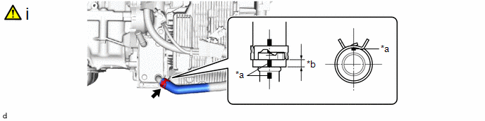
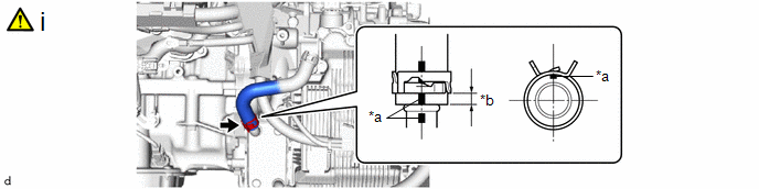
2. CONNECT NO. 2 WATER BY-PASS HOSE
|
*a |
Paint Mark |
*b |
2 to 6 mm (0.0787 to 0.236 in.) |
(1) Connect the No. 2 water by-pass hose to the transmission oil cooler and slide the hose clip to secure it.
NOTICE:
- Make sure to slide the No. 2 water by-pass hose until it contacts the hose stopper of the transmission oil cooler.
- Make sure to align the paint mark of the No. 2 water by-pass hose with the paint mark of the transmission oil cooler.
- Make sure that the claws of the hose clip are within the location shown in the illustration.
3. CONNECT INLET WATER HOSE
|
*a |
Paint Mark |
*b |
2 to 6 mm (0.0787 to 0.236 in.) |
(1) Connect the inlet water hose to the transmission oil cooler and slide the hose clip to secure it.
NOTICE:
- Make sure to slide the inlet water hose until it contacts the hose stopper of the transmission oil cooler.
- Make sure to align the paint mark of the inlet water hose with the paint mark of the transmission oil cooler.
- Make sure that the claws of the hose clip are within the location shown in the illustration.
4. ADD ENGINE COOLANT
Click here .gif)
5. ADJUST CONTINUOUSLY VARIABLE TRANSAXLE FLUID
Click here
6. INSPECT FOR COOLANT LEAK
Click here
7. INSPECT FOR CONTINUOUSLY VARIABLE TRANSAXLE FLUID LEAK
Click here
8. INSTALL REAR ENGINE UNDER COVER LH
9. INSTALL NO. 1 ENGINE UNDER COVER ASSEMBLY
Click here


