Toyota Corolla Cross: Removal
REMOVAL
CAUTION / NOTICE / HINT
COMPONENTS (REMOVAL)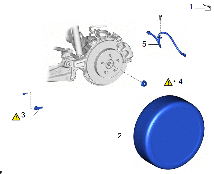
|
Procedure |
Part Name Code |
.png) |
.png) |
.png) |
|
|---|---|---|---|---|---|
|
1 |
DRAIN DIFFERENTIAL OIL |
- |
- |
|
- |
|
2 |
REAR WHEEL |
- |
- |
- |
- |
|
3 |
REAR SKID CONTROL SENSOR |
89544E |
|
- |
- |
|
4 |
REAR AXLE SHAFT NUT |
42312B |
|
- |
- |
|
5 |
REAR FLEXIBLE HOSE |
47319F |
- |
- |
- |
|
● |
Non-reusable part |
- |
- |
|
Procedure |
Part Name Code |
|
|
|
|
|---|---|---|---|---|---|
|
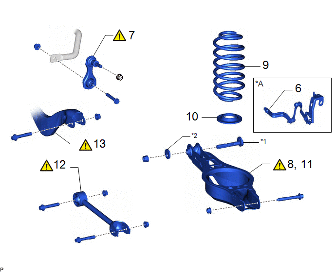
6 |
REAR HEIGHT CONTROL SENSOR SUB-ASSEMBLY LH |
89408C |
- |
- |
- |
|
7 |
REAR STABILIZER LINK ASSEMBLY |
48840A |
|
- |
- |
|
8 |
SEPARATE REAR NO. 2 SUSPENSION ARM ASSEMBLY |
48740F |
|
- |
- |
|
9 |
REAR COIL SPRING |
48231B |
- |
- |
- |
|
10 |
REAR LOWER COIL SPRING INSULATOR |
48258C |
- |
- |
- |
|
11 |
REMOVE REAR NO. 2 SUSPENSION ARM ASSEMBLY |
48740F |
|
- |
- |
|
12 |
REAR NO. 1 SUSPENSION ARM ASSEMBLY |
48720A |
|
- |
- |
|
13 |
REAR UPPER CONTROL ARM ASSEMBLY |
48790 |
|
- |
- |
|
*A |
for LH Side with Height Control Sensor |
- |
- |
|
*1 |
REAR SUSPENSION TOE ADJUST CAM SUB-ASSEMBLY |
*2 |
NO. 2 CAMBER ADJUST CAM |
|
Procedure |
Part Name Code |
|
|
|
|
|---|---|---|---|---|---|
|
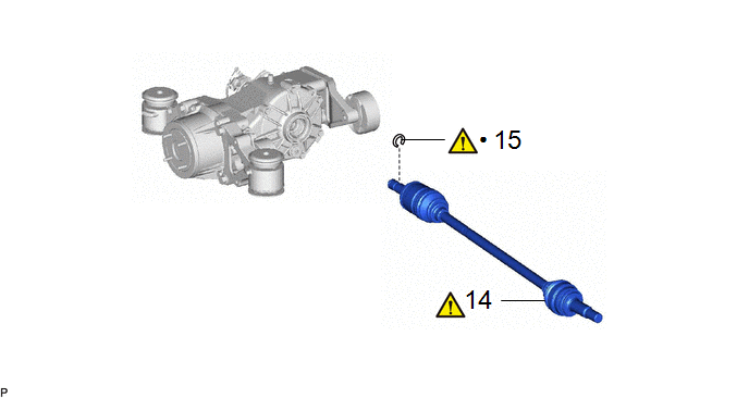
14 |
REAR DRIVE SHAFT ASSEMBLY |
42340B |
|
- |
- |
|
15 |
REAR DRIVE SHAFT INBOARD JOINT SHAFT SNAP RING |
42360M |
|
- |
- |
|
● |
Non-reusable part |
- |
- |
CAUTION / NOTICE / HINT
The necessary procedures (adjustment, calibration, initialization, or registration) that must be performed after parts are removed and installed, or replaced during the rear drive shaft assembly removal/installation are shown below.
Necessary Procedures After Parts Removed/Installed/Replaced|
Replacement Part or Procedure |
Necessary Procedures |
Effect/Inoperative Function When Necessary Procedures are not Performed |
Link |
|---|---|---|---|
|
Rear wheel alignment adjustment |
|
|
|
|
Reset memory |
Dynamic torque control AWD system |
|
|
|
Suspension, tires, etc. |
Rear television camera assembly optical axis (Back camera position setting) |
Parking assist monitor system |
|
|
Initialize headlight ECU sub-assembly LH |
Automatic headlight beam level control system |
|
HINT:
- Use the same procedure for the RH side and LH side.
- The following procedure is for the LH side.
PROCEDURE
1. DRAIN DIFFERENTIAL OIL
Click here .gif)
2. REMOVE REAR WHEEL
Click here
3. REMOVE REAR SKID CONTROL SENSOR
|
|
Click here |
4. REMOVE REAR AXLE SHAFT NUT
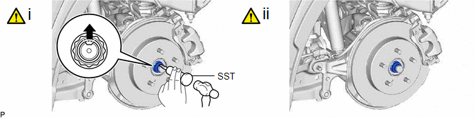
(1) Using SST and a hammer, release the staked part of the rear axle shaft nut.
SST: 09930-00010
NOTICE:
Loosen the staked part of the rear axle shaft nut completely, otherwise the threads of the rear drive shaft assembly may be damaged.
(2) Using a 30 mm deep socket wrench, remove the rear axle shaft nut while applying the brakes.
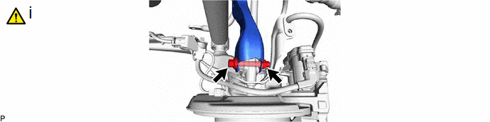
5. SEPARATE REAR FLEXIBLE HOSE
Click here
6. REMOVE REAR HEIGHT CONTROL SENSOR SUB-ASSEMBLY LH (for LH Side with Height Control Sensor)
Click here
7. REMOVE REAR STABILIZER LINK ASSEMBLY
|
|
Click here |
8. SEPARATE REAR NO. 2 SUSPENSION ARM ASSEMBLY
|
|
Click here |
9. REMOVE REAR COIL SPRING
Click here
10. REMOVE REAR LOWER COIL SPRING INSULATOR
Click here
11. REMOVE REAR NO. 2 SUSPENSION ARM ASSEMBLY
|
|
Click here |
12. REMOVE REAR NO. 1 SUSPENSION ARM ASSEMBLY
|
|
Click here |
13. SEPARATE REAR UPPER CONTROL ARM ASSEMBLY
(1) Remove the bolt and nut, and separate the rear upper control arm assembly from the rear axle carrier sub-assembly.
NOTICE:
Loosen the bolt with the nut secured.
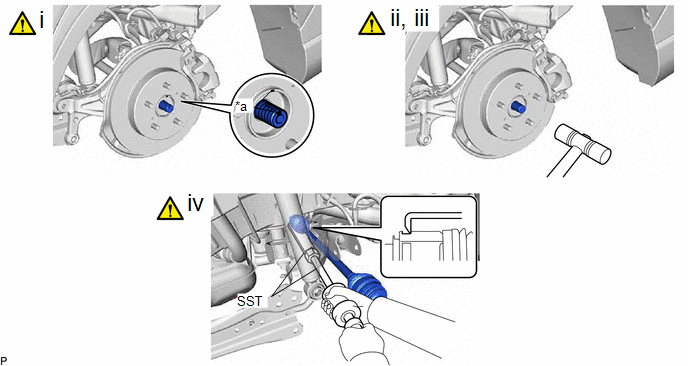
14. REMOVE REAR DRIVE SHAFT ASSEMBLY
|
*a |
Matchmark |
- |
- |
(1) Put matchmarks on the rear drive shaft assembly and the rear axle hub and bearing assembly.
(2) Using a plastic hammer, separate the rear drive shaft assembly from the rear axle hub and bearing assembly.
NOTICE:
- Do not push the rear axle hub and bearing assembly towards the outside of the vehicle any further than necessary.
- Do not damage the rear drive shaft outboard joint boot.
- Do not deform the rear disc brake dust cover sub-assembly.
- Do not damage the deflector.
(3) If it is difficult to separate the rear drive shaft assembly rear axle hub and bearing assembly, tap the end of the rear drive shaft assembly using a brass bar and a hammer.
(4) Using SST, remove the rear drive shaft assembly from the rear differential carrier assembly.
SST: 09520-01011
SST: 09520-20010
09521-02010
09521-02040
09521-02060
NOTICE:
- Do not damage the rear drive shaft oil seal.
- Do not damage the rear drive shaft inboard joint boot.
- Do not drop the rear drive shaft assembly.
- When removing the rear drive shaft assembly, keep it level.
15. REMOVE REAR DRIVE SHAFT INBOARD JOINT SHAFT SNAP RING
.png)
(1) Using a screwdriver, remove the rear drive shaft inboard joint shaft snap ring.


