Toyota Corolla Cross: Installation
INSTALLATION
CAUTION / NOTICE / HINT
COMPONENTS (INSTALLATION)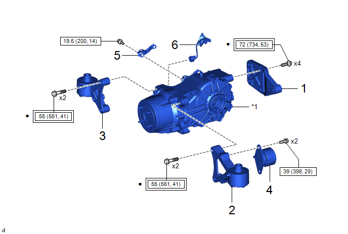
|
Procedure |
Part Name Code |
.png) |
.png) |
.png) |
|
|---|---|---|---|---|---|
|
1 |
REAR DIFFERENTIAL SUPPORT |
52391B |
- |
- |
- |
|
2 |
REAR NO. 2 DIFFERENTIAL SUPPORT |
52380C |
- |
- |
- |
|
3 |
REAR NO. 1 DIFFERENTIAL SUPPORT |
52380 |
- |
- |
- |
|
4 |
REAR DIFFERENTIAL DYNAMIC DAMPER |
41196 |
- |
- |
- |
|
5 |
WIRE HARNESS CLAMP BRACKET |
- |
- |
- |
- |
|
6 |
NO. 7 FLOOR WIRE |
8216A |
- |
- |
- |
|
*1 |
REAR DIFFERENTIAL CARRIER ASSEMBLY |
- |
- |
.png) |
Tightening torque for "Major areas involving basic vehicle performance such as moving/turning/stopping": N*m (kgf*cm, ft.*lbf) |
.png) |
N*m (kgf*cm, ft.*lbf): Specified torque |
|
● |
Non-reusable part |
- |
- |
|
Procedure |
Part Name Code |
|
|
|
|
|---|---|---|---|---|---|
|
7 |
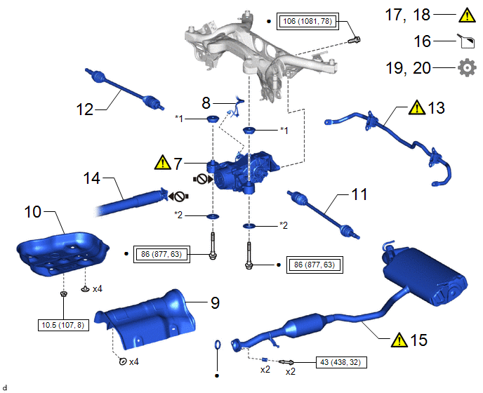
REAR DIFFERENTIAL CARRIER ASSEMBLY |
- |
|
- |
- |
|
8 |
NO. 2 FLOOR WIRE |
82162 |
- |
- |
- |
|
9 |
NO. 1 FUEL TANK PROTECTOR |
77641A |
- |
- |
- |
|
10 |
NO. 2 FUEL TANK PROTECTOR |
77642A |
- |
- |
- |
|
11 |
REAR DRIVE SHAFT ASSEMBLY LH |
42340B |
- |
- |
- |
|
12 |
REAR DRIVE SHAFT ASSEMBLY RH |
42330 |
- |
- |
- |
|
13 |
REAR STABILIZER BAR |
48812 |
|
- |
- |
|
14 |
PROPELLER SHAFT WITH CENTER BEARING ASSEMBLY |
37100 |
- |
- |
- |
|
15 |
TAIL EXHAUST PIPE ASSEMBLY |
17430 |
|
- |
- |
|
16 |
ADD DIFFERENTIAL OIL |
- |
- |
|
- |
|
17 |
INSPECT FOR DIFFERENTIAL OIL LEAK |
- |
|
- |
- |
|
18 |
INSPECT FOR EXHAUST GAS LEAK |
- |
|
- |
- |
|
19 |
INSPECT AND ADJUST REAR WHEEL ALIGNMENT |
- |
- |
- |
|
|
20 |
PERFORM INITIALIZATION |
- |
- |
- |
|
|
*1 |
REAR UPPER DIFFERENTIAL MOUNT STOPPER |
*2 |
REAR LOWER DIFFERENTIAL MOUNT STOPPER |
|
|
Tightening torque for "Major areas involving basic vehicle performance such as moving/turning/stopping": N*m (kgf*cm, ft.*lbf) |
|
N*m (kgf*cm, ft.*lbf): Specified torque |
|
● |
Non-reusable part |
.png) |
Do not apply lubricants |
PROCEDURE
1. INSTALL REAR DIFFERENTIAL SUPPORT
Torque:
72 N·m {734 kgf·cm, 53 ft·lbf}
2. INSTALL REAR NO. 2 DIFFERENTIAL SUPPORT
Torque:
55 N·m {561 kgf·cm, 41 ft·lbf}
3. INSTALL REAR NO. 1 DIFFERENTIAL SUPPORT
Torque:
55 N·m {561 kgf·cm, 41 ft·lbf}
4. INSTALL REAR DIFFERENTIAL DYNAMIC DAMPER
Torque:
39 N·m {398 kgf·cm, 29 ft·lbf}
5. INSTALL WIRE HARNESS CLAMP BRACKET
Torque:
19.6 N·m {200 kgf·cm, 14 ft·lbf}
6. INSTALL NO. 7 FLOOR WIRE
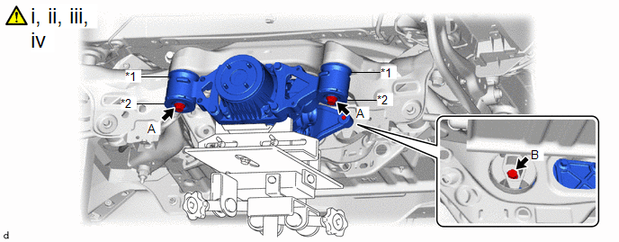
7. INSTALL REAR DIFFERENTIAL CARRIER ASSEMBLY
|
*1 |
Rear Upper Differential Mount Stopper |
*2 |
Rear Lower Differential Mount Stopper |
(1) Support the rear differential carrier assembly with a transmission jack.
NOTICE:
- The remaining oil may leak out when installing the rear differential carrier assembly.
- Securely support the rear differential carrier assembly while performing this step to avoid excessively tilting or dropping the rear differential carrier assembly.
(2) Temporarily install the rear differential carrier assembly, 2 rear upper differential mount stoppers and 2 rear lower differential mount stoppers to the rear suspension member sub-assembly with 3 new bolts.
(3) Tighten the 2 bolts (A).
Torque:
86 N·m {877 kgf·cm, 63 ft·lbf}
NOTICE:
Do not tighten the bolts with the inner cylinder or rear differential mount cushion tilted.
(4) Tighten the bolt (B).
Torque:
106 N·m {1081 kgf·cm, 78 ft·lbf}
NOTICE:
Do not tighten the bolts with the inner cylinder or rear differential mount cushion tilted.
8. CONNECT NO. 2 FLOOR WIRE
9. INSTALL NO. 1 FUEL TANK PROTECTOR
10. INSTALL NO. 2 FUEL TANK PROTECTOR
Click here .gif)
11. INSTALL REAR DRIVE SHAFT ASSEMBLY LH
Click here
12. INSTALL REAR DRIVE SHAFT ASSEMBLY RH
Click here
13. INSTALL REAR STABILIZER BAR
Click here
14. INSTALL PROPELLER SHAFT WITH CENTER BEARING ASSEMBLY
Click here
15. INSTALL TAIL EXHAUST PIPE ASSEMBLY
|
|
Click here |
16. ADD DIFFERENTIAL OIL
Click here
17. INSPECT FOR DIFFERENTIAL OIL LEAK
Click here
18. INSPECT FOR EXHAUST GAS LEAK
Click here
19. INSPECT AND ADJUST REAR WHEEL ALIGNMENT
Click here
20. PERFORM INITIALIZATION
|
Parking assist monitor system |
|
|
Automatic headlight beam level control system |
|


