Toyota Corolla Cross: Inspection
INSPECTION
PROCEDURE
1. INSPECT FRONT SEAT ADJUSTER ASSEMBLY
(a) Check the operation of the slide motor.
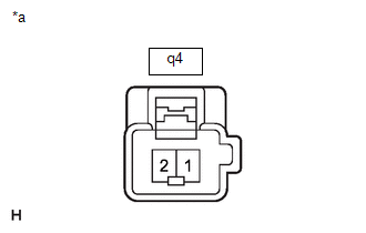
| (1) Check that the seat cushion moves smoothly when the auxiliary battery is connected to the slide motor connector terminals.
OK: |
Auxiliary Battery Connection |
Operational Direction | | Auxiliary battery positive (+) → q4-2
Auxiliary battery negative (-) → q4-1 |
Seat cushion moves forward | |
Auxiliary battery positive (+) → q4-1 Auxiliary battery negative (-) → q4-2 |
Seat cushion moves backward | If the result is not as specified, replace the front seat adjuster assembly. |
 |
|
*a | Component without harness connected
(Slide Motor (Front Seat Adjuster Assembly)) | | |
(b) Check the operation of the lifter motor.
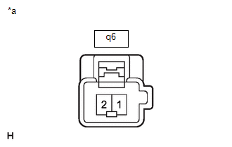
| (1) Check that the seat cushion moves smoothly when the auxiliary battery is connected to the lifter motor connector terminals.
OK: |
Auxiliary Battery Connection |
Operational Direction | |
Auxiliary battery positive (+) → q6-1 Auxiliary battery negative (-) → q6-2 |
Seat cushion moves upward | |
Auxiliary battery positive (+) → q6-2 Auxiliary battery negative (-) → q6-1 |
Seat cushion moves downward | If the result is not as specified, replace the front seat adjuster assembly. |
 |
|
*a | Component without harness connected
(Lifter Motor (Front Seat Adjuster Assembly)) | | |
(c) Check the operation of the front vertical motor.
| (1) Check that the seat cushion moves smoothly when the auxiliary battery is connected to the front vertical motor connector terminals.
OK: |
Auxiliary Battery Connection |
Operational Direction | |
Auxiliary battery positive (+) → q5-1 Auxiliary battery negative (-) → q5-2 |
Seat cushion moves upward | |
Auxiliary battery positive (+) → q5-2 Auxiliary battery negative (-) → q5-1 |
Seat cushion moves downward | If the result is not as specified, replace the front seat adjuster assembly. |
 |
|
*a | Component without harness connected
(Front Vertical Motor (Front Seat Adjuster Assembly)) | | |
2. INSPECT FRONT SEATBACK FRAME SUB-ASSEMBLY
(a) Check the operation of the reclining motor.
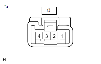
| (1) Check that the seatback moves smoothly when the auxiliary battery is connected to the reclining motor connector terminals.
OK: |
Auxiliary Battery Connection |
Operational Direction | |
Auxiliary battery positive (+) → r3-1 Auxiliary battery negative (-) → r3-4 |
Seatback moves forward | |
Auxiliary battery positive (+) → r3-4 Auxiliary battery negative (-) → r3-1 |
Seatback moves backward | If the result is not as specified, replace the front seatback frame sub-assembly. |
 |
|
*a | Component without harness connected
(Reclining Motor (Front Seatback Frame Sub-assembly)) | | |
READ NEXT:
REASSEMBLY CAUTION / NOTICE / HINT COMPONENTS (REASSEMBLY)
Procedure Part Name Code
1 SEAT TRACK REAR UPPER COVER
72125V -
- -
2 SEAT T
INSTALLATION CAUTION / NOTICE / HINT COMPONENTS (INSTALLATION)
Procedure Part Name Code
1 FRONT SEAT ASSEMBLY
-
- -
2 SEAT TRACK
SEE MORE:
DESCRIPTION
The E.F.I. vacuum sensor assembly detects the intake manifold pressure as a change in voltage. The ECM calculates the intake manifold pressure based on this voltage. The ECM calculates the EGR valve assembly and purge VSV (No. 1 vacuum switching valve assembly) opening amount accordin
DESCRIPTION
Detection Item
Symptom
Trouble Area
Power Steering ECU Communication Stop Mode
Communication stop for "Power Steering (EPS)" is indicated on the "Communication
Bus Check" screen of the GTS.
Click her


