Toyota Corolla Cross: Inspection
INSPECTION
PROCEDURE
1. INSPECT REAR DOOR LOCK WITH MOTOR ASSEMBLY LH
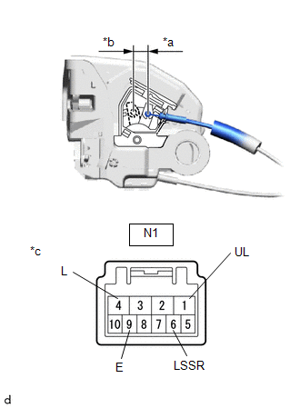
| (a) Check the door lock motor operation. (1) Apply auxiliary battery voltage to the motor connector and check the operation of the door lock motor.
OK: |
Measurement Condition |
Specified Condition | |
Auxiliary battery positive (+) → N1-4 (L) Auxiliary battery negative (-) → N1-1 (UL) |
Lock | | Auxiliary battery positive (+) → N1-1 (UL)
Auxiliary battery negative (-) → N1-4 (L) |
Unlock | If the result is not as specified, replace the rear door lock with motor assembly LH. |
 |
|
*a | Unlock | |
*b | Lock | |
*c | Component without harness connected
(Rear Door Lock with Motor Assembly LH) | | |
(b) Check the operation of the door unlock detection switch.
(1) Measure the resistance according to the value(s) in the table below.
Standard Resistance:
|
Tester Connection | Condition |
Specified Condition |
|
N1-6 (LSSR) - N1-9 (E) |
Lock | 10 kΩ or higher |
|
Unlock | Below 1 Ω |
If the result is not as specified, replace the rear door lock with motor assembly LH.
2. INSPECT REAR DOOR LOCK WITH MOTOR ASSEMBLY RH
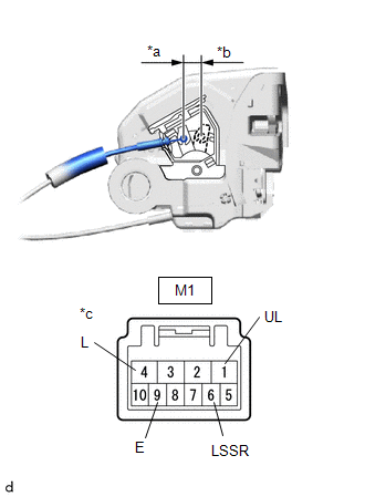
| (a) Check the door lock motor operation. (1) Apply auxiliary battery voltage to the motor connector and check the operation of the door lock motor.
OK: |
Measurement Condition |
Specified Condition | |
Auxiliary battery positive (+) → M1-4 (L) Auxiliary battery negative (-) → M1-1 (UL) |
Lock | | Auxiliary battery positive (+) → M1-1 (UL)
Auxiliary battery negative (-) → M1-4 (L) |
Unlock | If the result is not as specified, replace the rear door lock with motor assembly RH. |
 |
|
*a | Unlock | |
*b | Lock | |
*c | Component without harness connected
(Rear Door Lock with Motor Assembly RH) | | |
(b) Check the operation of the unlock detection switch.
(1) Measure the resistance according to the value(s) in the table below.
Standard Resistance:
|
Tester Connection | Condition |
Specified Condition |
|
M1-6 (LSSR) - M1-9 (E) |
Lock | 10 kΩ or higher |
|
Unlock | Below 1 Ω |
If the result is not as specified, replace the rear door lock with motor assembly RH.
READ NEXT:
INSTALLATION CAUTION / NOTICE / HINT COMPONENTS (INSTALLATION)
Procedure Part Name Code
1 REAR DOOR LOCK AND UNLOCK KNOB INSIDE LOCKING CABLE
69780E -
RemovalREMOVAL CAUTION / NOTICE / HINT COMPONENTS (REMOVAL)
Procedure Part Name Code
1 STEERING WHEEL POSITION
-
- -
2 LOWER STE
RemovalREMOVAL CAUTION / NOTICE / HINT COMPONENTS (REMOVAL)
Procedure Part Name Code
1 FRONT WHEEL LH
- -
- -
2 FRONT FENDER MOULDING S
SEE MORE:
INSTALLATION CAUTION / NOTICE / HINT COMPONENTS (INSTALLATION)
Procedure Part Name Code
1 CHILD RESTRAINT SEAT ANCHOR BRACKET SUB-ASSEMBLY
73705C
- -
2 REAR SEAT CUSHION LOCK HOOK
72693 -
- -
3 BENCH TY
DESCRIPTION The HV battery is composed of 60 cells (3.7 V each) in series. The battery ECU assembly monitors the internal resistance of each HV battery cell to detect malfunctions of the HV battery.
DTC No. Detection Item
DTC Detection Condition
Trouble Area MIL
Warning


