Toyota Corolla Cross: Installation
INSTALLATION
CAUTION / NOTICE / HINT
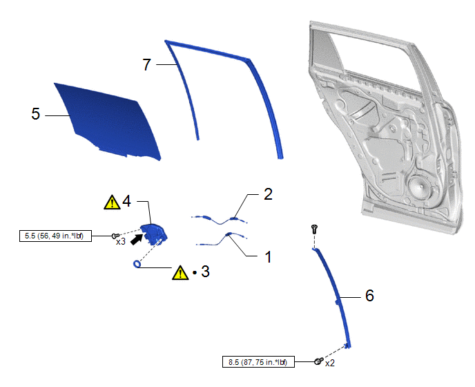
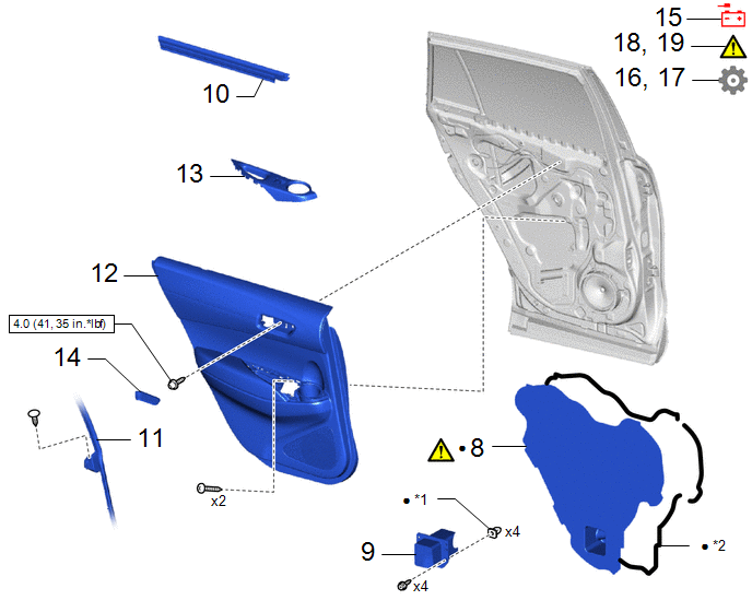
COMPONENTS (INSTALLATION)
|
Procedure | Part Name Code |
.png) |
.png) |
 |
|---|---|---|---|---|---|
|
1 | REAR DOOR LOCK AND UNLOCK KNOB INSIDE LOCKING CABLE |
69780E | - |
- | - |
|
2 | OPEN LEVER REAR DOOR LOCK REMOTE CONTROL CABLE |
69740E | - |
- | - |
|
3 | DOOR LOCK WIRING HARNESS SEAL |
69318D |
|
- | - |
|
4 | REAR DOOR LOCK WITH MOTOR ASSEMBLY |
69060A |
|
- | - |
|
5 | REAR DOOR GLASS SUB-ASSEMBLY |
68104 | - |
- | - |
|
6 | REAR DOOR WINDOW DIVISION BAR SUB-ASSEMBLY |
67408H | - |
- | - |
|
7 | REAR DOOR GLASS RUN |
68152C | - |
- | - |
.png) |
N*m (kgf*cm, ft.*lbf): Specified torque |
● | Non-reusable part |
.png) |
MP grease | - |
- |

|
Procedure | Part Name Code |
.png) |
.png) |
 |
|---|---|---|---|---|---|
|
8 | REAR DOOR SERVICE HOLE COVER |
67842E |
|
- | - |
|
9 | REAR DOOR INSIDE PANEL REINFORCE SUB-ASSEMBLY |
67058 | - |
- | - |
|
10 | REAR DOOR GLASS INNER WEATHERSTRIP |
68174A | - |
- | - |
|
11 | REAR DOOR WEATHERSTRIP |
67872 | - |
- | - |
|
12 | REAR DOOR TRIM BOARD SUB-ASSEMBLY |
67604 | - |
- | - |
|
13 | REAR POWER WINDOW REGULATOR SWITCH ASSEMBLY WITH REAR DOOR ARMREST BASE PANEL |
- | - |
- | - |
|
14 | REAR DOOR INSIDE HANDLE BEZEL PLUG |
69284G | - |
- | - |
|
15 | CONNECT CABLE TO NEGATIVE AUXILIARY BATTERY TERMINAL |
- | - |
- | - |
|
16 | INITIALIZATION AFTER RECONNECTING AUXILIARY BATTERY TERMINAL |
- | - |
- |
|
|
17 | INITIALIZE POWER WINDOW CONTROL SYSTEM |
- | - |
- |
|
|
18 | INSPECT POWER WINDOW OPERATION |
- |
|
- | - |
|
19 | INSPECT POWER DOOR LOCK CONTROL SYSTEM |
- |
|
- | - |
|
*1 | GROMMET |
*2 | BUTYL TAPE |
.png) |
N*m (kgf*cm, ft.*lbf): Specified torque |
● | Non-reusable part |
CAUTION / NOTICE / HINT
HINT:
- Use the same procedure for the RH side and LH side.
- The following procedure is for the LH side.
PROCEDURE
1. INSTALL REAR DOOR LOCK AND UNLOCK KNOB INSIDE LOCKING CABLE
2. INSTALL OPEN LEVER REAR DOOR LOCK REMOTE CONTROL CABLE
3. INSTALL DOOR LOCK WIRING HARNESS SEAL
.png) |
NOTICE: When reusing the rear door lock with motor assembly. |
4. INSTALL REAR DOOR LOCK WITH MOTOR ASSEMBLY
.png) |
NOTICE:
|

.png) |
MP Grease | - |
- |
(1) Apply MP grease to the sliding parts of the rear door lock with motor assembly.

|
*1 | Release Plate |
- | - |
.png) |
Install in this Direction |
- | - |
(1) Connect the release plate as shown in the illustration.
HINT:
Make sure that the release plate is securely connected to the rear door lock with motor assembly.
(2) Using a T30 "TORX" socket wrench, install the rear door lock with motor assembly with the 3 screws.
Torque:
5.5 N·m {56 kgf·cm, 49 in·lbf}
(3) Connect the connector.
5. INSTALL REAR DOOR GLASS SUB-ASSEMBLY
6. INSTALL REAR DOOR WINDOW DIVISION BAR SUB-ASSEMBLY
Click here .gif)
7. INSTALL REAR DOOR GLASS RUN
8. INSTALL REAR DOOR SERVICE HOLE COVER
.png) |
Click here |
9. INSTALL REAR DOOR INSIDE PANEL REINFORCE SUB-ASSEMBLY
10. INSTALL REAR DOOR GLASS INNER WEATHERSTRIP
11. CONNECT REAR DOOR WEATHERSTRIP
12. INSTALL REAR DOOR TRIM BOARD SUB-ASSEMBLY
Click here .gif)
13. INSTALL REAR POWER WINDOW REGULATOR SWITCH ASSEMBLY WITH REAR DOOR ARMREST BASE PANEL
14. INSTALL REAR DOOR INSIDE HANDLE BEZEL PLUG
15. CONNECT CABLE TO NEGATIVE AUXILIARY BATTERY TERMINAL
- for Gasoline Model
Click here
.gif)
- for HEV Model
Click here
.gif)
16. INITIALIZATION AFTER RECONNECTING AUXILIARY BATTERY TERMINAL
HINT:
When disconnecting and reconnecting the auxiliary battery, there is an automatic learning function that completes learning when the respective system is used.
Click here .gif)
17. INITIALIZE POWER WINDOW CONTROL SYSTEM
Click here .gif)
18. INSPECT POWER WINDOW OPERATION
Click here .gif)
19. INSPECT POWER DOOR LOCK CONTROL SYSTEM
Click here .gif)


