Toyota Corolla Cross: Inspection
INSPECTION
PROCEDURE
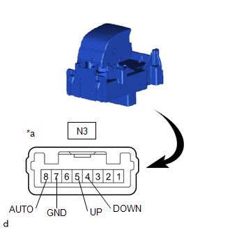
1. INSPECT REAR POWER WINDOW REGULATOR SWITCH ASSEMBLY (for LH Side)
(a) Check the resistance.
| (1) Measure the resistance according to the value(s) in the table below.
Standard Resistance: |
Tester Connection | Condition |
Specified Condition | |
N3-5 (UP) - N3-7 (GND) |
Auto up or up position |
Below 100 Ω | |
N3-4 (DOWN) - N3-7 (GND) |
Auto down or down position |
Below 100 Ω | |
N3-8 (AUTO) - N3-7 (GND) |
Auto up or auto down position |
Below 100 Ω | |
N3-5 (UP) - N3-7 (GND) |
Off | 10 kΩ or higher | |
N3-4 (DOWN) - N3-7 (GND) |
Off | 10 kΩ or higher | |
N3-8 (AUTO) - N3-7 (GND) |
Off | 10 kΩ or higher |
If the result is not as specified, replace the rear power window regulator switch assembly. |
 |
|
*a | Component without harness connected
(Rear Power Window Regulator Switch Assembly) | | |
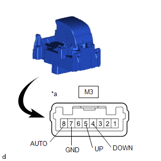
2. INSPECT REAR POWER WINDOW REGULATOR SWITCH ASSEMBLY (for RH Side)
(a) Check the resistance.
| (1) Measure the resistance according to the value(s) in the table below.
Standard Resistance: |
Tester Connection | Condition |
Specified Condition | |
M3-5 (UP) - M3-7 (GND) |
Auto up or up position |
Below 100 Ω | |
M3-4 (DOWN) - M3-7 (GND) |
Auto down or down position |
Below 100 Ω | |
M3-8 (AUTO) - M3-7 (GND) |
Auto up or auto down position |
Below 100 Ω | |
M3-5 (UP) - M3-7 (GND) |
Off | 10 kΩ or higher | |
M3-4 (DOWN) - M3-7 (GND) |
Off | 10 kΩ or higher | |
M3-8 (AUTO) - M3-7 (GND) |
Off | 10 kΩ or higher |
If the result is not as specified, replace the rear power window regulator switch assembly. |
 |
|
*a | Component without harness connected
(Rear Power Window Regulator Switch Assembly) | | |
READ NEXT:
INSTALLATION CAUTION / NOTICE / HINT COMPONENTS (INSTALLATION)
Procedure Part Name Code
1 REAR POWER WINDOW REGULATOR SWITCH ASSEMBLY
84810D -
- -
On-vehicle InspectionON-VEHICLE INSPECTION PROCEDURE
1. INSPECT FRONT WIPER DEICER RELAY (a) Check the resistance.
(1) Measure the resistance according to the value(s) in the table below.
Stan
SEE MORE:
REMOVAL CAUTION / NOTICE / HINT COMPONENTS (REMOVAL)
Procedure Part Name Code
1 FUEL SUCTION TUBE WITH PUMP AND GAUGE ASSEMBLY
77020A -
- -
2 FUEL SENDER GAUGE ASSEMBLY
83320
- -
*1 FUEL GAUGE BRACKET
On-vehicle InspectionON-VEHICLE INSPECTION CAUTION / NOTICE / HINT
CAUTION: Do not remove the reserve tank cap and air release valve while the engine and radiator assembly are still hot. Pressurized, hot engine coolant and steam may be released and cause serious burns.
PROCEDURE 1. INSPECT FOR


