Toyota Corolla Cross: Hybrid/EV Battery Air Temperature Sensor "A" Circuit Short to Ground (P0AAC11,P0AAC15)
DESCRIPTION
The inlet air temperature sensor (HV battery) is mounted on the HV battery. The resistance of the sensor varies in accordance with changes in the intake air temperature. The characteristics of the inlet air temperature sensor are the same as those of the battery temperature sensors (Click here
.gif) ). The battery ECU assembly uses signals from the inlet air temperature sensor to control the air volume of the battery cooling blower assembly.
). The battery ECU assembly uses signals from the inlet air temperature sensor to control the air volume of the battery cooling blower assembly.
|
DTC No. | Detection Item |
DTC Detection Condition |
Trouble Area | MIL |
Warning Indicate | Note |
|---|---|---|---|---|---|---|
|
P0AAC11 | Hybrid/EV Battery Air Temperature Sensor "A" Circuit Short to Ground |
The inlet air temperature sensor output voltage is lower than the specified value (short circuit) and the detected temperature is higher than the specified value. (1 trip detection logic) |
| Does not come on |
Master Warning: Comes on |
SAE Code: P0AAE |
|
P0AAC15 | Hybrid/EV Battery Air Temperature Sensor "A" Circuit Short to Auxiliary Battery or Open |
The inlet air temperature sensor output voltage is higher than the standard value (short to +B or open) and the detected temperature is lower than the specified value. (1 trip detection logic) |
| Does not come on |
Master Warning: Comes on |
SAE Code: P0AAF |
HINT:
After checking for the above DTCs, check the hybrid system Data List item "Hybrid/EV Battery Cooling Fan Intake Air Temperature 1" using the GTS.
|
Displayed Temperature |
Malfunction |
|---|---|
|
-45°C (-49°F) or less |
Open or +B short circuit |
|
95°C (203°F) or more |
GND short |
CONFIRMATION DRIVING PATTERN
HINT:
After repair has been completed, clear the DTC and then check that the vehicle has returned to normal by performing the following All Readiness check procedure.
Click here
- Connect the GTS to the DLC3.
- Turn the ignition switch to ON and turn the GTS on.
- Clear the DTCs (even if no DTCs are stored, perform the clear DTC procedure).
- Turn the ignition switch off and wait for 2 minutes or more.
- Turn the ignition switch to ON and turn the GTS on.
- With ignition switch ON and wait for 5 seconds or more.
- Enter the following menus: Powertrain / HV Battery / Utility / All Readiness.
- Check the DTC judgment result.
HINT:
- If the judgment result shows NORMAL, the system is normal.
- If the judgment result shows ABNORMAL, the system has a malfunction.
- If the judgment result shows INCOMPLETE, perform driving pattern again.
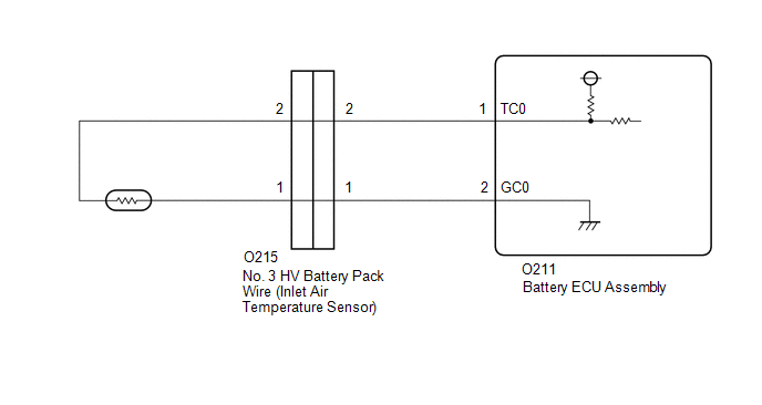
WIRING DIAGRAM
CAUTION / NOTICE / HINT
CAUTION:
Refer to the precautions before inspecting high voltage circuit.
Click here
NOTICE:
- After the ignition switch is turned off, there may be a waiting time before disconnecting the negative (-) auxiliary battery terminal.
Click here
- When disconnecting and reconnecting the auxiliary battery
HINT:
When disconnecting and reconnecting the auxiliary battery, there is an automatic learning function that completes learning when the respective system is used.
Click here
PROCEDURE
|
1. | CHECK DTC OUTPUT (HV BATTERY, HYBRID CONTROL) |
(a) Check for DTCs.
Powertrain > HV Battery > Trouble Codes Powertrain > Hybrid Control > Trouble Codes|
Result | Proceed to |
|---|---|
|
"P0AAC11 or P0AAC15" only is output, or DTCs except the ones in the table below are also output. |
A |
| DTCs of hybrid battery system in the table below are output. |
B |
| DTCs of hybrid control system in the table below are output. |
C |
|
System | Relevant DTC | |
|---|---|---|
|
Hybrid battery system |
P060A47 | Hybrid/EV Battery Energy Control Module Monitoring Processor Watchdog / Safety MCU Failure |
|
P060B49 | Hybrid/EV Battery Energy Control Module A/D Processing Internal Electronic Failure | |
|
P060687 | Hybrid/EV Battery Energy Control Module Processor to Monitoring Processor Missing Message | |
|
Hybrid control system |
P0A1F94 | Hybrid/EV Battery Energy Control Module Unexpected Operation |
(b) Turn the ignition switch off.
| B | .gif) | GO TO DTC CHART (HYBRID BATTERY SYSTEM) |
| C | | GO TO DTC CHART (HYBRID CONTROL SYSTEM) |
|
.gif)
|
2. | CHECK CONNECTOR CONNECTION CONDITION (BATTERY ECU ASSEMBLY CONNECTOR) |
CAUTION:
Be sure to wear insulated gloves and protective goggles.
(a) Check that the service plug grip is not installed.
NOTICE:
After removing the service plug grip, do not turn the ignition switch to ON (READY), unless instructed by the repair manual because this may cause a malfunction.
| (b) Check the connector connections and contact pressure of the relevant terminals for the battery ECU assembly. Click here OK: The connector is connected securely and there are no contact problems. |
|
.png)
| NG | | CONNECT SECURELY |
|
|
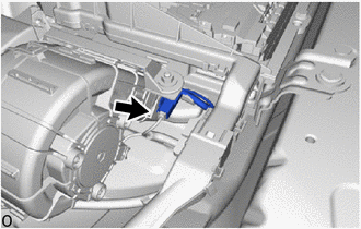
3. | CHECK INSTALLATION OF INLET AIR TEMPERATURE SENSOR |
CAUTION:
Be sure to wear insulated gloves and protective goggles.
(a) Check that the service plug grip is not installed.
NOTICE:
After removing the service plug grip, do not turn the ignition switch to ON (READY), unless instructed by the repair manual because this may cause a malfunction.
(b) Disconnect the high voltage connector from the HV battery junction block assembly.
NOTICE:
Insulate each disconnected high-voltage connector with insulating tape. Wrap the connector from the wire harness side to the end of the connector.
| (c) Visually check the installation condition of the inlet air temperature sensor. Result:
|
|
(d) Reconnect the high voltage connector to the HV battery junction block assembly.
| B | | REPLACE NO. 3 HV BATTERY PACK WIRE |
| C | | INSTALL PARTS CORRECTLY |
|
|
4. | CHECK BATTERY ECU ASSEMBLY (BATTERY CURRENT SENSOR OUTPUT VOLTAGE) |
CAUTION:
Be sure to wear insulated gloves and protective goggles.
(a) Check that the service plug grip is not installed.
NOTICE:
After removing the service plug grip, do not turn the ignition switch to ON (READY), unless instructed by the repair manual because this may cause a malfunction.
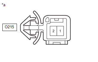
(b) Disconnect the No. 3 HV battery pack wire (inlet air temperature sensor) connector.
NOTICE:
Before disconnecting the connector, check that it is not loose or disconnected.
(c) Connect the cable to the negative (-) auxiliary battery terminal.
(d) Turn the ignition switch to ON.
(e) Measure the voltage according to the value (s) in the table below.
Standard Voltage:
|
Tester Connection | Switch Condition |
Specified Condition |
|---|---|---|
|
O215-2 - O215-1 | Ignition switch ON |
4.5 to 5.5 V |
NOTICE:
Be sure not to damage or deform the terminal being inspected.
(f) Turn the ignition switch off.
(g) Disconnect the cable from the negative (-) auxiliary battery terminal.
(h) Reconnect the No. 3 HV battery pack wire (inlet air temperature sensor) connectors.
| NG | | GO TO STEP 6 |
|
|
5. | CHECK NO. 3 HV BATTERY PACK WIRE (INLET AIR TEMPERATURE SENSOR) |
CAUTION:
Be sure to wear insulated gloves and protective goggles.
(a) Check that the service plug grip is not installed.
NOTICE:
After removing the service plug grip, do not turn the ignition switch to ON (READY), unless instructed by the repair manual because this may cause a malfunction.
(b) Disconnect the No. 3 HV battery pack wire (inlet air temperature sensor) connector.
NOTICE:
Before disconnecting the connector, check that it is not loose or disconnected.
| (c) Measure the resistance according to the value (s) in the table below. Standard Resistance:
|
|
(d) Reconnect the No. 3 HV battery pack wire (inlet air temperature sensor) connector.
| OK | | REPLACE HV BATTERY |
| NG | | REPLACE NO. 3 HV BATTERY PACK WIRE |
|
6. | CHECK HARNESS AND CONNECTOR (BATTERY ECU ASSEMBLY - NO. 3 HV BATTERY PACK WIRE) |
CAUTION:
Be sure to wear insulated gloves and protective goggles.
(a) Check that the service plug grip is not installed.
NOTICE:
After removing the service plug grip, do not turn the ignition switch to ON (READY), unless instructed by the repair manual because this may cause a malfunction.
(b) Disconnect the battery ECU assembly connector.
(c) Disconnect the No. 3 HV battery pack wire (inlet air temperature sensor) connector.
(d) Measure the resistance according to the value (s) in the table below.
Standard Resistance (Check for Open):
|
Tester Connection | Condition |
Specified Condition |
|---|---|---|
|
O211-1 (TC0) - O215-2 |
Ignition switch off |
Below 1 Ω |
|
O211-2 (GC0) - O215-1 |
Ignition switch off |
Below 1 Ω |
Standard Resistance (Check for Short):
|
Tester Connection | Condition |
Specified Condition |
|---|---|---|
|
O211-1 (TC0) or O215-2 - Body ground and other terminals |
Ignition switch off |
10 kΩ or higher |
|
O211-2 (GC0) or O215-1 - Body ground and other terminals |
Ignition switch off |
10 kΩ or higher |
(e) Reconnect the battery ECU assembly connector.
(f) Reconnect the No. 3 HV battery pack wire (inlet air temperature sensor) connector.
| OK | | REPLACE BATTERY ECU ASSEMBLY |
| NG | | REPAIR OR REPLACE HARNESS OR CONNECTOR |
READ NEXT:
 Hybrid/EV Battery Current Sensor "A" Circuit Short to Ground (P0ABF11,P0ABF15,P0B0E11,P0B0E15,P1CBB12,P1CBB14)
DESCRIPTION A battery current sensor, which is mounted on the positive cable side of each HV battery junction block assembly, detects the current flowing to or from the battery pack. The battery curre
Hybrid/EV Battery Current Sensor "A" Signal Bias Level Out of Range / Zero Adjustment Failure (P0ABF28)
DESCRIPTION Refer to the description for DTC P0ABF11.
Click here
DTC No. Detection Item
DTC Detection Condition
Trouble Area MIL
Warning Indicate Note
P0AB
Hybrid/EV Battery Current Sensor "A" Signal Stuck In Range (P0ABF2A)
DESCRIPTION Refer to the description for DTC P0ABF11.
Click here
DTC No. Detection Item
DTC Detection Condition
Trouble Area MIL
Warning Indicate Note
P0AB
SEE MORE:
 Driver Side Electrical Antenna Circuit Open (B27A113)
DESCRIPTION The certification ECU (smart key ECU assembly) generates a request signal and transmits the signal to the front door outside handle assembly LH (electrical key antenna) at intervals of 0.25 seconds. For the front door outside handle assembly LH (electrical key antenna) to detect when the
Disposal
DISPOSAL CAUTION / NOTICE / HINT
CAUTION: Before performing pre-disposal deployment of any SRS part, review and closely follow all applicable environmental and hazardous material regulations. Pre-disposal deployment may be considered hazardous material treatment. PROCEDURE
1. PRECAUTION
CAUTIO
