Toyota Corolla Cross: Inspection
INSPECTION
PROCEDURE
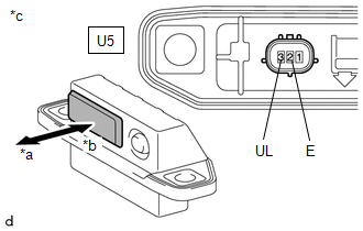
1. INSPECT BACK DOOR OPENER SWITCH ASSEMBLY (w/ Smart Key System)
(a) Check the operation of the opener switch.
| (1) Measure the resistance according to the value(s) in the table below.
Standard Resistance: |
Tester Connection | Condition |
Specified Condition | |
U5-3 (UL) - U5-2 (E) |
Back door opener switch pushed (ON) |
Below 1 Ω | |
U5-3 (UL) - U5-2 (E) |
Back door opener switch not pushed (OFF) |
10 kΩ or higher | If the result is not as specified, replace the back door opener switch assembly. |
 |
|
*a | Not Pushed (OFF) | |
*b | Pushed (ON) | |
*c | Component without harness connected
(Back Door Opener Switch Assembly) | | |
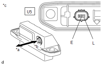
| (b) Check the operation of the back door lock switch. (1) Measure the resistance according to the value(s) in the table below.
Standard Resistance: |
Tester Connection | Condition |
Specified Condition | |
U5-1 (L) - U5-2 (E) |
Back door lock switch pushed (ON) |
Below 1 Ω | |
U5-1 (L) - U5-2 (E) |
Back door lock switch not pushed (OFF) |
10 kΩ or higher | If the result is not as specified, replace the back door opener switch assembly. |
 |
|
*a | Not Pushed (OFF) | |
*b | Pushed (ON) | |
*c | Component without harness connected
(Back Door Opener Switch Assembly) | | |
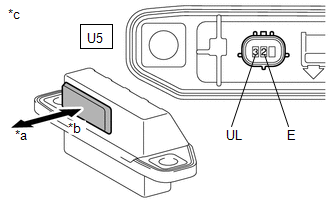
2. INSPECT BACK DOOR OPENER SWITCH ASSEMBLY (w/o Smart Key System)
(a) Check the operation of the opener switch.
| (1) Measure the resistance according to the value(s) in the table below.
Standard Resistance: |
Tester Connection | Condition |
Specified Condition | |
U5-3 (UL) - U5-2 (E) |
Back door opener switch pushed (ON) |
Below 1 Ω | |
U5-3 (UL) - U5-2 (E) |
Back door opener switch not pushed (OFF) |
10 kΩ or higher | If the result is not as specified, replace the back door opener switch assembly. |
 |
|
*a | Not Pushed (OFF) | |
*b | Pushed (ON) | |
*c | Component without harness connected
(Back Door Opener Switch Assembly) | | |
READ NEXT:
INSTALLATION CAUTION / NOTICE / HINT COMPONENTS (INSTALLATION)
Procedure Part Name Code
1 BACK DOOR OPENER SWITCH ASSEMBLY
84840G -
- -
2 BACK D
REMOVAL CAUTION / NOTICE / HINT COMPONENTS (REMOVAL)
Procedure Part Name Code
1 BACK DOOR STAY ASSEMBLY
68960B
- -
2 BACK DOOR DAMPER STAY
SEE MORE:
ComponentsCOMPONENTS ILLUSTRATION
*1 TONGUE PLATE STOPPER
- -
● Non-reusable part
- - ReplacementREPLACEMENT PROCEDURE
1. REMOVE TONGUE PLATE STOPPER
(a) Slide the tongue plate above the installation position of the tongue plate stopper, and tempora
DTC SUMMARY MALFUNCTION DESCRIPTION This DTC is stored when the motor generator control system is malfunctioning and current does not flow as commanded. The cause of this malfunction may be one of the following:
Area Main Malfunction Description
Inside of inverter
Inverter w


