Toyota Corolla Cross: Inspection
INSPECTION
PROCEDURE
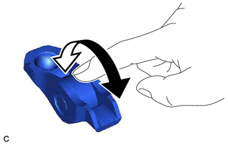
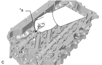
1. INSPECT NO. 1 VALVE ROCKER ARM SUB-ASSEMBLY
| (a) Turn the roller by hand to check that it turns smoothly. HINT: If the roller does not turn smoothly, replace the No. 1 valve rocker arm sub-assembly. |
|
2. INSPECT VALVE LASH ADJUSTER ASSEMBLY
NOTICE:
- Keep the valve lash adjuster assembly free from dirt and foreign matter.
- Only use clean engine oil.
(a) Place the valve lash adjuster assembly into a container filled with engine oil.
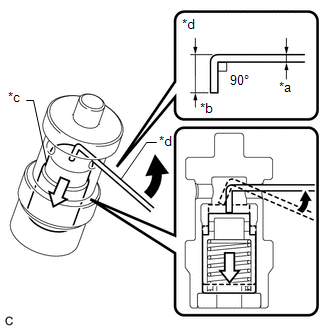
(b) Insert the tip of SST into the valve lash adjuster assembly plunger and use the tip to press down on the check ball inside the plunger.
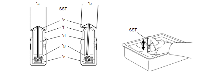
|
*a | Correct |
*b | Incorrect |
|
*c | Tapered Path |
*d | Low Pressure Chamber |
|
*e | High Pressure Chamber |
*f | Plunger |
|
*g | Check Ball | - |
- |
SST: 09276-75010
(c) Squeeze SST and the valve lash adjuster assembly together to move the plunger up and down 5 to 6 times.
(d) Check the movement of the plunger and bleed the air.
OK:
Plunger moves up and down.
NOTICE:
When bleeding air from the high-pressure chamber, make sure that the tip of SST is pressing the check ball as shown in the illustration. If the check ball is not pressed, air will not bleed.
(e) After bleeding the air, remove SST. Then try to quickly and firmly press the plunger by hand.
OK:
The plunger is very difficult to move.
HINT:
If the plunger is easy to move, replace the valve lash adjuster assembly.
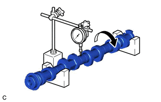
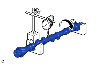
3. INSPECT INTAKE CAMSHAFT SUB-ASSEMBLY
| (a) Inspect the intake camshaft sub-assembly for runout. (1) Place the intake camshaft sub-assembly on V-blocks. (2) Using a dial indicator, measure the runout at the center journal. Maximum Runout: 0.03 mm (0.00118 in.) HINT:
|
|
| (b) Inspect the cam lobes. (1) Using a micrometer, measure the cam lobe height. Standard Cam Lobe Height: 42.615 to 42.715 mm (1.67775 to 1.68169 in.) Minimum Cam Lobe Height: 42.157 mm (1.65972 in.) HINT: If the cam lobe height is less than the minimum, replace the intake camshaft sub-assembly. |
|
| (c) Inspect the intake camshaft sub-assembly journals. (1) Using a micrometer, measure the journal diameter. Standard Journal Diameter:
HINT: If the journal diameter is not as specified, check the intake camshaft sub-assembly oil clearance. Click here |
|
4. INSPECT EXHAUST CAMSHAFT SUB-ASSEMBLY
| (a) Inspect the exhaust camshaft sub-assembly for runout. (1) Place the exhaust camshaft sub-assembly on V-blocks. (2) Using a dial indicator, measure the runout at the center journal. Maximum Runout: 0.03 mm (0.00118 in.) HINT:
|
|
| (b) Inspect the cam lobes. (1) Using a micrometer, measure the cam lobe height. Standard Cam Lobe Height:
Minimum Cam Lobe Height:
HINT: If the cam lobe height is less than the minimum, replace the exhaust camshaft sub-assembly. |
|
| (c) Inspect the exhaust camshaft sub-assembly journals. (1) Using a micrometer, measure the journal diameter. Standard Journal Diameter:
HINT: If the journal diameter is not as specified, check the camshaft oil clearance. Click here |
|
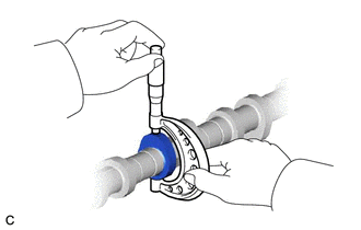
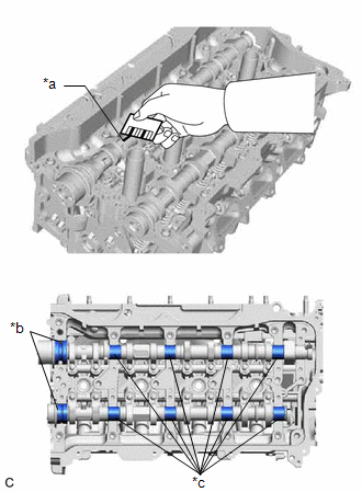
5. INSPECT CAMSHAFT OIL CLEARANCE
(a) Clean the No. 1 camshaft bearing cap, No. 2 camshaft bearing cap, 2 No. 3 camshaft bearing caps, camshaft housing sub-assembly and camshaft journals.
(b) Place the intake camshaft sub-assembly and exhaust camshaft sub-assembly on the camshaft housing sub-assembly.
| (c) Lay a strip of Plastigage across each of the camshaft journals. |
|
(d) Install the camshaft bearing caps.
Click here
.gif)
NOTICE:
Do not turn the camshafts.
(e) Remove the camshaft bearing caps.
Click here
| (f) Measure the Plastigage at its widest point. Standard Oil Clearance (for Intake Camshaft Sub-assembly):
Standard Oil Clearance (for Exhaust Camshaft Sub-assembly):
Maximum Oil Clearance (for Intake Camshaft Sub-assembly):
Maximum Oil Clearance (for Exhaust Camshaft Sub-assembly):
NOTICE: Completely remove the Plastigage after the inspection. HINT: If the oil clearance is more than the maximum, replace the intake camshaft sub-assembly or exhaust camshaft sub-assembly. If necessary, replace the camshaft housing sub-assembly. |
|
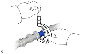
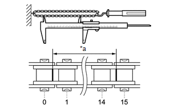
6. INSPECT CHAIN SUB-ASSEMBLY
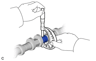
| (a) Using a spring scale, pull the chain sub-assembly with a force of 147 N (15 kgf, 33.0 lbf) as shown in the illustration. |
|

(b) Using a vernier caliper, measure the length of 15 links.
Maximum Chain Elongation:
116.30 mm (4.58 in.)
NOTICE:
Perform the measurement at 3 random places. Use the average of the measurements.
HINT:
If the average elongation is more than the maximum, replace the chain sub-assembly.
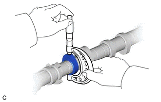
7. INSPECT OIL PUMP DRIVE CHAIN SUB-ASSEMBLY
| (a) Using a spring scale, pull the oil pump drive chain sub-assembly with a force of 147 N (15 kgf, 33.0 lbf) as shown in the illustration. |
|
(b) Using a vernier caliper, measure the length of 15 links.
Maximum Chain Elongation:
116.30 mm (4.58 in.)
NOTICE:
Perform the measurement at 3 random places. Use the average of the measurements.
HINT:
If the average elongation is more than the maximum, replace the oil pump drive chain sub-assembly.
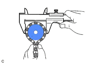
8. INSPECT OIL PUMP DRIVE SPROCKET
| (a) Place the oil pump drive chain sub-assembly around the oil pump drive sprocket. |
|
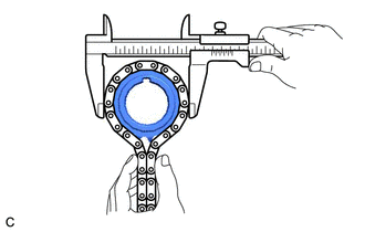
(b) Using a vernier caliper, measure the diameter of the oil pump drive sprocket and oil pump drive chain sub-assembly.
Minimum Gear Diameter (with Oil Pump Drive Chain Sub-assembly):
51.35 mm (2.02 in.)
NOTICE:
The vernier caliper must be in contact with the chain rollers when measuring.
HINT:
If the diameter is less than the minimum, replace the oil pump drive chain sub-assembly and oil pump drive sprocket.
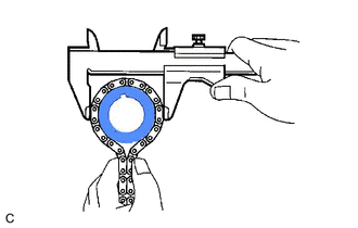
9. INSPECT OIL PUMP DRIVE SHAFT SPROCKET
| (a) Place the oil pump drive chain sub-assembly around the oil pump drive shaft sprocket. |
|
(b) Using a vernier caliper, measure the diameter of the oil pump drive shaft sprocket and oil pump drive chain sub-assembly.
Minimum Gear Diameter (with Oil Pump Drive Chain Sub-assembly):
51.35 mm (2.02 in.)
NOTICE:
The vernier caliper must be in contact with the chain rollers when measuring.
HINT:
If the diameter is less than the minimum, replace the oil pump drive chain sub-assembly and oil pump drive shaft sprocket.
10. INSPECT CAMSHAFT TIMING GEAR ASSEMBLY
| (a) Place the chain sub-assembly around the camshaft timing gear assembly. |
|
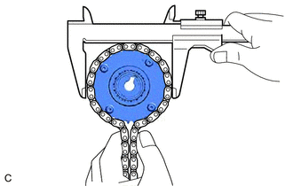
(b) Using a vernier caliper, measure the diameter of the camshaft timing gear assembly and chain sub-assembly.
Minimum Gear Diameter (with Chain Sub-assembly):
100.01 mm (3.94 in.)
NOTICE:
The vernier caliper must be in contact with the chain rollers when measuring.
HINT:
If the diameter is less than the minimum, replace the chain sub-assembly and camshaft timing gear assembly.
11. INSPECT CAMSHAFT TIMING EXHAUST GEAR ASSEMBLY
| (a) Place the chain sub-assembly around the camshaft timing exhaust gear assembly. |
|

(b) Using a vernier caliper, measure the diameter of the camshaft timing exhaust gear assembly and chain sub-assembly.
Minimum Gear Diameter (with Chain Sub-assembly):
100.01 mm (3.94 in.)
NOTICE:
The vernier caliper must be in contact with the chain rollers when measuring.
HINT:
If the diameter is less than the minimum, replace the chain sub-assembly and camshaft timing exhaust gear assembly.
12. INSPECT CRANKSHAFT TIMING SPROCKET
| (a) Place the chain sub-assembly around the crankshaft timing sprocket. |
|
(b) Using a vernier caliper, measure the diameter of the crankshaft timing sprocket and chain sub-assembly.
Minimum Sprocket Diameter (with Chain Sub-assembly):
51.35 mm (2.02 in.)
NOTICE:
The vernier caliper must be in contact with the chain rollers when measuring.
HINT:
If the diameter is less than the minimum, replace the chain sub-assembly and crankshaft timing sprocket.
13. INSPECT NO. 1 CHAIN TENSIONER ASSEMBLY
| (a) Push the plunger and check that it moves smoothly. HINT: If the plunger does not move smoothly, replace the No. 1 chain tensioner assembly. |
|

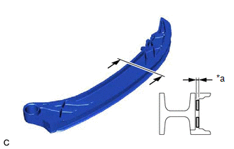
14. INSPECT CHAIN TENSIONER SLIPPER
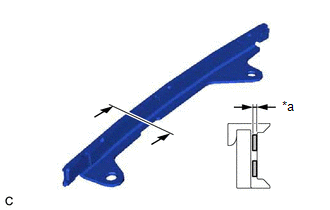
| (a) Using a vernier caliper, measure the wear depth of the chain tensioner slipper. Maximum Depth: 1.0 mm (0.0394 in.) HINT: If the depth is more than the maximum, replace the chain tensioner slipper. |
|
15. INSPECT NO. 1 CHAIN VIBRATION DAMPER
| (a) Using a vernier caliper, measure the wear depth of the No. 1 chain vibration damper. Maximum Depth: 1.0 mm (0.0394 in.) HINT: If the depth is more than the maximum, replace the No. 1 chain vibration damper. |
|
16. INSPECT CYLINDER HEAD SET BOLT
(a) for 140 mm cylinder head set bolt:
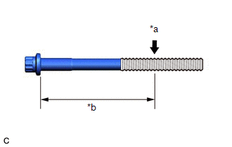
| (1) Using a vernier caliper, measure the diameter of the threads at the measurement point. Standard Diameter: 10.7 to 10.9 mm (0.421 to 0.429 in.) Minimum Diameter: 10.6 mm (0.417 in.) Measurement Point (Distance from the Seat): 105 mm (4.13 in.) HINT:
|
|
(b) for 130 mm cylinder head set bolt:
| (1) Using a vernier caliper, measure the diameter of the threads at the measurement point. Standard Diameter: 9.7 to 9.9 mm (0.382 to 0.390 in.) Minimum Diameter: 9.6 mm (0.378 in.) Measurement Point (Distance from the Seat): 115 mm (4.53 in.) HINT:
|
|
17. INSPECT EXHAUST MANIFOLD (TWC: Front Catalyst)
| (a) Using a precision straightedge and feeler gauge, check the surface that contacts the cylinder head sub-assembly for warpage. Maximum Warpage: 0.7 mm (0.0276 in.) HINT: If the warpage is more than the maximum, replace the exhaust manifold (TWC: Front Catalyst). |
|
18. INSPECT OIL NOZZLE VALVE SUB-ASSEMBLY
(a) Using a piece of wire, check that the check valve is not stuck.
|
*a | 1 mm (0.0394 in.) |
|
*b | 5 mm (0.197 in.) |
|
*c | Check Valve |
|
*d | Wire |
.png) |
Move the wire in this direction. |
.png) |
Movement of Check Valve |
HINT:
- Form a 1 mm (0.0394 in.) diameter piece of wire to the shape shown in the illustration.
- If the check valve is stuck, replace the oil nozzle valve sub-assembly with a new one.
| (b) Connect a hose to the oil nozzle valve sub-assembly. |
|
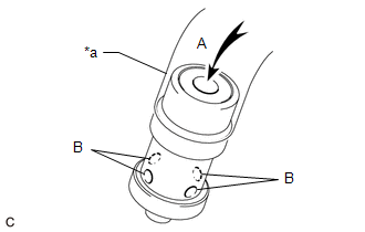
(c) Check that air does not leak from the port (B) when blowing air into the port (A).
HINT:
If air leaks from the port (B), replace the oil nozzle valve sub-assembly with a new one.
(d) With the check valve depressed using a piece of wire, check that air flows from the port (B) when blowing air into the port (A).
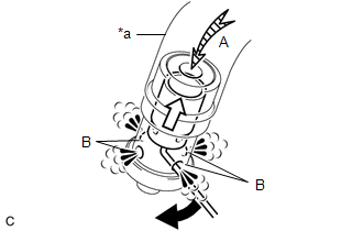
|
*a | Hose |
|
|
Move the wire in this direction. |
|
|
Movement of Check Valve |
HINT:
If air does not flow from the port (B), replace the oil nozzle valve sub-assembly with a new one.
(e) Disconnect the hose from the oil nozzle valve sub-assembly.


