Toyota Corolla Cross: Reassembly
REASSEMBLY
CAUTION / NOTICE / HINT
COMPONENTS (REASSEMBLY).png)
|
Procedure |
Part Name Code |
.png) |
.png) |
.png) |
|
|---|---|---|---|---|---|
|
1 |
UNIVERSAL BOOT KIT |
- |
|
- |
- |
.gif)
|
*1 |
FRONT PROPELLER SHAFT ASSEMBLY |
*2 |
NO. 1 DUST DEFLECTOR |
|
*3 |
CENTER SUPPORT BEARING |
*4 |
FLANGE |
|
*5 |
SMALL DIAMETER PROPELLER SHAFT BOOT CLAMP |
*6 |
PROPELLER SHAFT BOOT |
|
*7 |
TRIPOD JOINT |
*8 |
PROPELLER SHAFT SNAP RING |
|
*9 |
LARGE DIAMETER PROPELLER SHAFT BOOT CLAMP |
*10 |
BEARING CASE SNAP RING |
|
*11 |
REAR PROPELLER SHAFT ASSEMBLY |
- |
- |
|
● |
Non-reusable part |
- |
- |
CAUTION / NOTICE / HINT
NOTICE:
- As imbalance affects vibration and noise performance, make sure to ensure
correct angular alignment of the following components during installation.
- FRONT PROPELLER SHAFT ASSEMBLY
- REAR PROPELLER SHAFT ASSEMBLY
- LARGE DIAMETER PROPELLER SHAFT BOOT CLAMP
- SMALL DIAMETER PROPELLER SHAFT BOOT CLAMP
- TRIPOD JOINT
PROCEDURE
1. INSTALL UNIVERSAL BOOT KIT
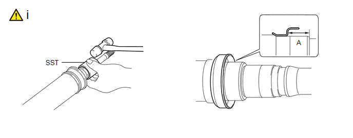
(1) Using SST and a plastic hammer, install a new No. 1 dust deflector to the dimension (A).
SST: 09710-18050
09711-01090
Dimension (A):
17.2 to 17.6 mm (0.678 to 0.692 in.)
NOTICE:
Do not excessively press the No. 1 dust deflector.
|
*a |
Turn |
*b |
Hold |
|
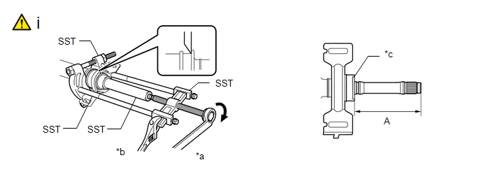
*c |
Flange |
- |
- |
(1) Using SST, install a new center support bearing and flange to the front propeller shaft assembly to the dimension (A).
SST: 09612-22011
SST: 09950-00020
SST: 09950-00040
SST: 09950-40011
09951-04020
09952-04010
09953-04020
09954-04040
09957-04010
Dimension (A):
117.95 to 119.85 mm (4.65 to 4.71 in.)
HINT:
Perform this procedure with 2 or more people and prevent the propeller shaft from rotating.
|
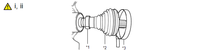
*1 |
Small Diameter Propeller Shaft Boot Clamp |
*2 |
Propeller Shaft Boot |
|
*3 |
Large Diameter Propeller Shaft Boot Clamp |
- |
- |
(1) Install each new parts to the front propeller shaft assembly in the order shown in the illustration.
(2) Install the small diameter side of the propeller shaft boot to the front propeller shaft assembly.
|
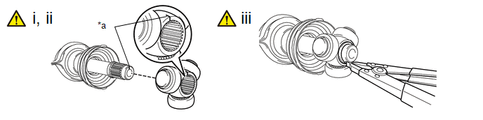
*a |
Matchmark |
- |
- |
(1) Align the matchmarks and install the tripod joint to the front propeller shaft assembly.
NOTICE:
Face the serrated side of the tripod joint outward and install it to the joint end.
(2) Using a brass bar and a hammer, install the tripod joint.
NOTICE:
- Do not tap the rollers.
- Keep the tripod joint free of foreign matter.
- Be careful not to drop the tripod joint.
(3) Using a snap ring expander, install a new propeller shaft snap ring.
NOTICE:
Make sure to securely install the propeller shaft snap ring.
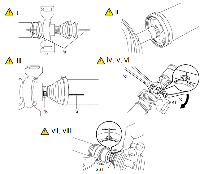
|
*a |
Matchmark |
*b |
Crimp position |
|
*c |
Turn |
*d |
Hold |
(1) Align the matchmark and insert the front propeller shaft assembly into the rear propeller shaft assembly.
(2) Install a new bearing case snap ring to the rear propeller shaft assembly.
HINT:
Make sure to securely install the bearing case snap ring.
(3) Align the crimp position of the small diameter propeller shaft boot clamp with the matchmark of the rear propeller shaft assembly.
(4) Place SST onto the small diameter propeller shaft boot clamp, and while pushing it against the propeller shaft boot, slightly tighten the bolt of SST.
SST: 09521-24010
(5) While holding SST, tighten the bolt of SST until the specified clearance value of the small diameter propeller shaft boot clamp is met.
Clearance:
Below 0.8 mm (0.0315 in.)
(6) Remove SST.
(7) Using SST, measure the clearance shown in the illustration.
SST: 09240-00021
Clearance:
Below 0.8 mm (0.0315 in.)
NOTICE:
If the clearance is not as specified, retighten SST.
(8) Fill the rear propeller shaft assembly and propeller shaft boot with grease.
Standard Grease Capacity:
106 to 116 g (3.74 to 4.09 oz)
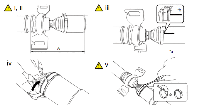
|
*a |
Matchmark |
*b |
Crimp position |
(1) Install the propeller shaft boot to the rear propeller shaft assembly to the specified value (A).
(2) Measure the distance (A) of the propeller shaft assembly shown in the illustration. If the value is not as specified, reinstall the propeller shaft boot.
Dimension (A):
191.2 to 193.6 mm (7.53 to 7.62 in.)
(3) Align the crimp position of the large diameter propeller shaft boot clamp with the matchmark of the rear propeller shaft assembly.
(4) Temporarily bend the lever from the fulcrum part of the large diameter propeller shaft boot clamp.
(5) Using a screwdriver, stake the large diameter propeller shaft boot clamp.
NOTICE:
Be careful not to damage the propeller shaft boot.
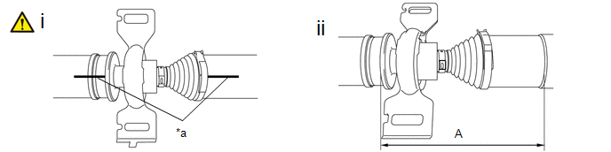
|
*a |
Matchmark |
- |
- |
(1) Confirm that the matchmarks of the front propeller shaft assembly and rear propeller shaft assembly are aligned.
(2) Check whether the front propeller shaft assembly dimension (A) is within specification.
Dimension (A):
191.2 to 193.6 mm (7.53 to 7.62 in.)


