Toyota Corolla Cross: Initialization
INITIALIZATION
INITIALIZE POWER WINDOW CONTROL SYSTEM (ALL DOORS)
NOTICE:
- When a power window regulator motor assembly, door window regulator sub-assembly, door belt moulding or door glass weatherstrip inner have been removed and installed, or if a power window regulator motor assembly was reused when a door glass or door glass run was replaced, the power window control system must be initialized. Functions such as the auto up and down function, jam protection function, catch protection function, remote control function, key-linked function, wireless transmitter-linked function, key-off operation function and window open warning function will not operate if initialization is not performed.
- When a power window regulator motor assembly is replaced, DTC B2313 is stored. Clear the DTC after initialization.
Click here
Click here
.gif)
- When performing initialization, do not perform any other procedures.
- When performing initialization, use the power window switch of each door to initialize each power window.
- If initialization cannot be completed properly, the LIN communication system may be malfunctioning.
Click here
- Make sure to park the vehicle and turn off all electrical systems before performing initialization. Initialization will be canceled if the vehicle is driven during initialization.
- Make sure not to hit, strike or vibrate the door glass during initialization because the vehicle is learning the sliding resistance of the door glass.
- Make sure not to turn the ignition switch off during initialization.
HINT:
If the auxiliary battery has been replaced, it is not necessary to initialize the power window regulator motor assemblies.
(a) Perform initialization according to the table below.
|
Condition of Power Window |
Proceed to |
|---|---|
| Power window regulator motor assembly has been replaced with a new one. |
Procedure A |
HINT: Use this procedure if a power window regulator motor assembly is being reused. |
Procedure B |
| Power window unexpectedly operates in reverse or stops due to a change in the sliding resistance after a fitting adjustment is made. |
Procedure C |
(b) Procedure A
(1) Perform window position initialization (fully closed, fully open) and sliding resistance learning.
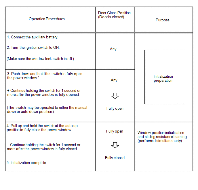
HINT:
*: Even if the door glass is in the fully open position before performing step 3, push down and hold the switch for 1 second or more.
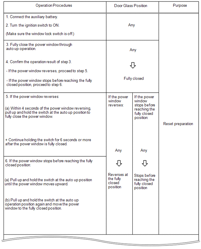
(c) Procedure B
(1) Perform window position initialization (fully closed, fully open) and sliding resistance learning.
Reset the power window position, perform window position initialization (fully closed, fully opened) and sliding resistance learning.
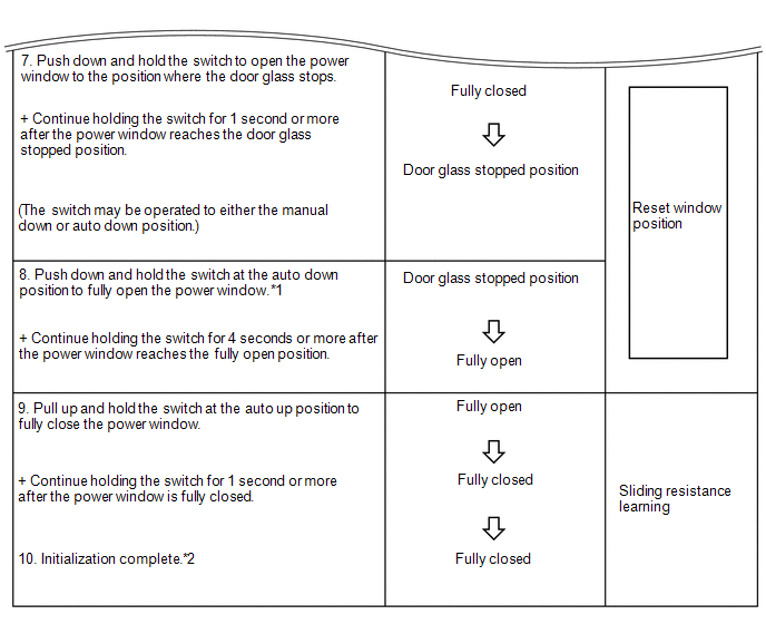
HINT:
- *1: After performing step 7, release the switch, and then perform an auto down operation.
- *2: After completing initialization, check that the power window can be fully closed using an auto up operation.
If initialization cannot be completed properly, the LIN communication system may be malfunctioning.
Click here
(d) Procedure C
(1) Perform sliding resistance learning.
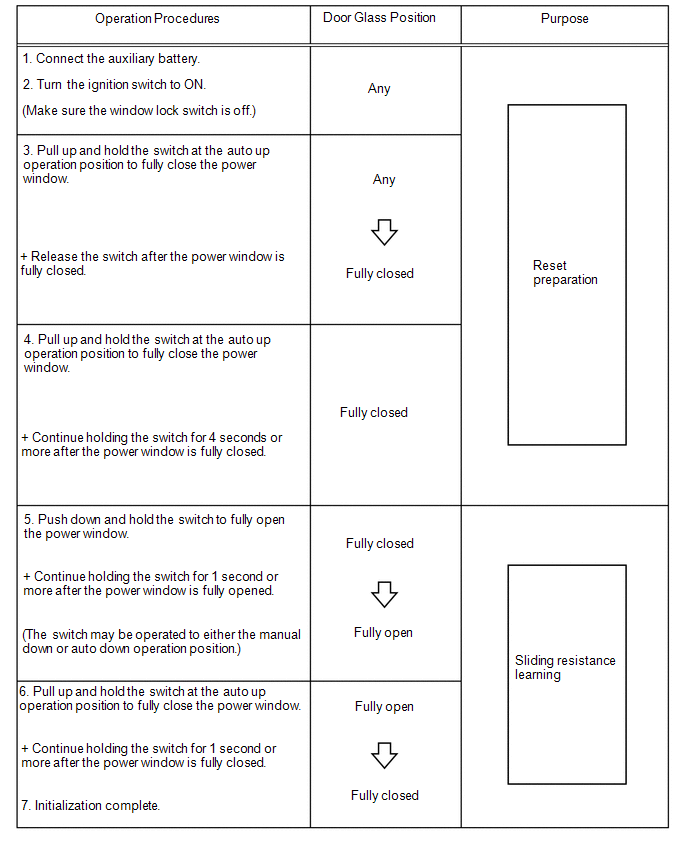
HINT:
If the jam protection function or catch protection function continues to operate even after performing steps 4, 5 and 6, perform the procedure again from step 3.


