Toyota Corolla Cross: Image from Camera for Rear View Monitor is Abnormal
DESCRIPTION
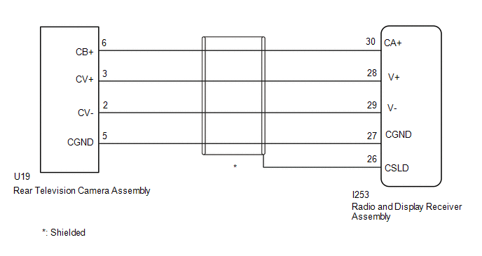
The display signal from the rear television camera assembly is transmitted to the radio and display receiver assembly.
WIRING DIAGRAM

CAUTION / NOTICE / HINT
NOTICE:
- When replacing the radio and display receiver assembly, always replace
it with a new one.
If a radio and display receiver assembly which was installed to another vehicle is used, the following may occur:
- A communication malfunction DTC may be stored.
- The radio and display receiver assembly may not operate normally.
Click here
.gif)
PROCEDURE
|
1. |
CHECK HARNESS AND CONNECTOR (RADIO AND DISPLAY RECEIVER ASSEMBLY - REAR TELEVISION CAMERA ASSEMBLY) |
(a) Disconnect the I253 radio and display receiver assembly connector.
(b) Disconnect the U19 rear television camera assembly connector.
(c) Measure the resistance according to the value(s) in the table below.
Standard Resistance:
|
Tester Connection |
Condition |
Specified Condition |
|---|---|---|
|
I253-30 (CA+) - U19-6 (CB+) |
Always |
Below 1 Ω |
|
I253-28 (V+) - U19-3 (CV+) |
Always |
Below 1 Ω |
|
I253-27 (CGND) - U19-5 (CGND) |
Always |
Below 1 Ω |
|
I253-29 (V-) - U19-2 (CV-) |
Always |
Below 1 Ω |
|
I253-30 (CA+) or U19-6 (CB+) - Body ground |
Always |
10 kΩ or higher |
|
I253-28 (V+) or U19-3 (CV+) - Body ground |
Always |
10 kΩ or higher |
|
I253-27 (CGND) or U19-5 (CGND) - Body ground |
Always |
10 kΩ or higher |
|
I253-29 (V-) or U19-2 (CV-) - Body ground |
Always |
10 kΩ or higher |
|
I253-26 (CSLD) - Body ground |
Always |
10 kΩ or higher |
| NG | .gif)
|
REPAIR OR REPLACE HARNESS OR CONNECTOR |
|
|
2. |
CHECK RADIO AND DISPLAY RECEIVER ASSEMBLY |
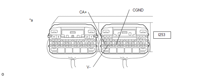
(a) Remove the radio and display receiver assembly with its connectors still connected.

|
*a |
Component with harness connected (Radio and Display Receiver Assembly) |
- |
- |
(b) Measure the resistance according to the value(s) in the table below.
Standard Resistance:
|
Tester Connection |
Condition |
Specified Condition |
|---|---|---|
|
I253-29 (V-) - Body ground |
Always |
Below 1 Ω |
|
I253-27 (CGND) - Body ground |
Always |
Below 1 Ω |
(c) Measure the voltage according to the value(s) in the table below.
Standard Voltage:
|
Tester Connection |
Switch Condition |
Specified Condition |
|---|---|---|
|
I253-30 (CA+) - Body ground |
Ignition switch ACC |
5.5 to 7.05 V |
| NG | .gif)
|
REPLACE RADIO AND DISPLAY RECEIVER ASSEMBLY |
|
|
3. |
CHECK REAR TELEVISION CAMERA ASSEMBLY |
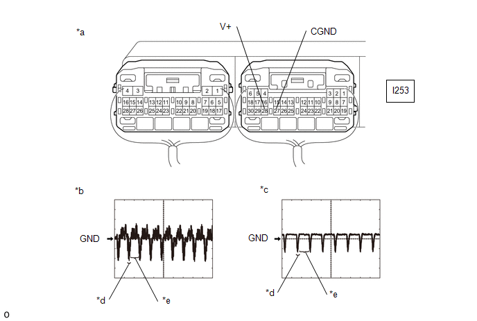
(a) Remove the radio and display receiver assembly with its connectors still connected.

|
*a |
Component with harness connected (Radio and Display Receiver Assembly) |
*b |
Waveform 1 |
|
*c |
Waveform 2 |
*d |
Synchronization Signal |
|
*e |
Video Waveform |
- |
- |
(b) Check the waveform of the rear television camera assembly using an oscilloscope.
HINT:
- A waterproof connector is used for the television camera assembly. Therefore, inspect the waveform at the radio and display receiver assembly with the connector connected.
- The video waveform changes according to the image sent by the rear television camera assembly.
|
Item |
Content |
|---|---|
|
Terminal No. (Symbol) |
I253-28 (V+) - I253-27 (CGND) |
|
Tool Setting |
200 mV/DIV., 50 μsec./DIV. |
|
Condition |
Waveform 1: Ignition switch ON, shift lever in R, camera lens not covered, displaying an image Waveform 2: Ignition switch ON, shift lever in R, camera lens covered, blacking out screen |
OK:
Waveform is as shown in the illustration.
| OK | .gif)
|
REPLACE RADIO AND DISPLAY RECEIVER ASSEMBLY |
|
|
4. |
CHECK REAR TELEVISION CAMERA ASSEMBLY |
(a) Replace the rear television camera assembly with a new or known good one.
Click here .gif)
(b) Check if the same malfunction recurs when the rear view monitor screen is displayed.
OK:
Malfunction does not reoccur (returns to normal).
| OK | .gif)
|
END (REAR TELEVISION CAMERA ASSEMBLY WAS DEFECTIVE) |
| NG | .gif)
|
REPLACE RADIO AND DISPLAY RECEIVER ASSEMBLY |

.gif)

