Toyota Corolla Cross: Television Camera
Removal
REMOVAL
CAUTION / NOTICE / HINT
COMPONENTS (REMOVAL)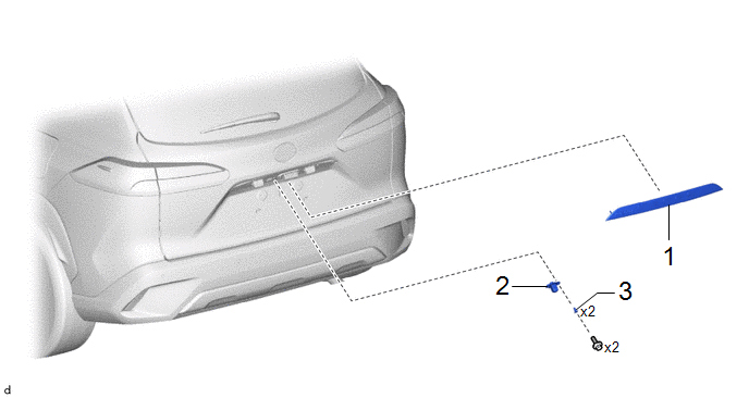
|
Procedure |
Part Name Code |
.png) |
.png) |
.png) |
|
|---|---|---|---|---|---|
|
1 |
BACK DOOR OUTSIDE GARNISH SUB-ASSEMBLY |
- |
- |
- |
- |
|
2 |
TELEVISION CAMERA ASSEMBLY |
86790D |
- |
- |
- |
|
3 |
SCREW GROMMET |
- |
- |
- |
- |
CAUTION / NOTICE / HINT
The necessary procedures (adjustment, calibration, initialization or registration) that must be performed after parts are removed and installed, or replaced during television camera assembly removal/installation are shown below.
Necessary Procedures After Parts Removed/Installed/Replaced|
Replaced Part or Performed Procedure |
Necessary Procedure |
Effect/Inoperative Function when Necessary Procedure not Performed |
Link |
|---|---|---|---|
|
Rear television camera assembly |
|
Parking assist monitor system |
|
PROCEDURE
1. REMOVE BACK DOOR OUTSIDE GARNISH SUB-ASSEMBLY
Click here .gif)
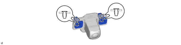
2. REMOVE TELEVISION CAMERA ASSEMBLY
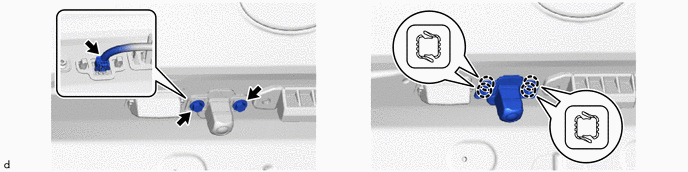
3. REMOVE SCREW GROMMET
Installation
INSTALLATION
CAUTION / NOTICE / HINT
COMPONENTS (INSTALLATION)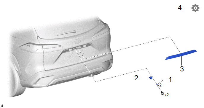
|
Procedure |
Part Name Code |
.png) |
.png) |
.png) |
|
|---|---|---|---|---|---|
|
1 |
SCREW GROMMET |
- |
- |
- |
- |
|
2 |
TELEVISION CAMERA ASSEMBLY |
86790D |
- |
- |
- |
|
3 |
BACK DOOR OUTSIDE GARNISH SUB-ASSEMBLY |
- |
- |
- |
- |
|
4 |
ADJUST TELEVISION CAMERA ASSEMBLY |
86790D |
- |
- |
|
PROCEDURE
1. INSTALL SCREW GROMMET
2. INSTALL TELEVISION CAMERA ASSEMBLY
3. INSTALL BACK DOOR OUTSIDE GARNISH SUB-ASSEMBLY
Click here .gif)
4. ADJUST TELEVISION CAMERA ASSEMBLY
Click here


