Toyota Corolla Cross: Ignition Switch On/Start Position Circuit Low Circuit Short to Ground or Open (P253314)
DTC SUMMARY
The hybrid vehicle control ECU stores a DTC when there is no auxiliary battery voltage to the IGR terminal even though there is auxiliary battery voltage to the IGP terminal.
DESCRIPTION
When the ignition switch is turned to ON, the auxiliary battery power source is supplied to the IGP and IGR terminals of the hybrid vehicle control ECU. When the ignition switch is off, the auxiliary battery power source is cut off.
When the ignition switch is turned off during driving, the auxiliary battery power source supplied to the IGP terminal is cut off. However, the auxiliary battery power source supplied to the IGR terminal is supplied until the vehicle is stopped and the ignition switch is turned off.
|
DTC No. | Detection Item |
DTC Detection Condition |
Trouble Area | MIL |
Warning Indicate | Note |
|---|---|---|---|---|---|---|
|
P253314 | Ignition Switch On/Start Position Circuit Low Circuit Short to Ground or Open |
Short to ground or open in IGR terminal circuit. (2 trip detection logic) |
| Does not come on |
Master Warning: Does not come on |
SAE Code: P2534 |
CONFIRMATION DRIVING PATTERN
HINT:
After repair has been completed, clear the DTCs and then check that the vehicle has returned to normal by performing the following All Readiness check procedure.
Click here .gif)
- Clear the DTCs (even if no DTCs are stored, perform the clear DTC procedure).
- Turn the ignition switch off and wait for at least 30 seconds.
- Turn the ignition switch to ON (READY) and wait for 1 minute or more.
- Enter the following menus: Powertrain / Engine / Utility / All Readiness.
- Check the DTC judgment result.
HINT:
- If the judgment result shows NORMAL, the system is normal.
- If the judgment result shows ABNORMAL, the system has a malfunction.
- If the judgment result shows INCOMPLETE, perform driving pattern again.
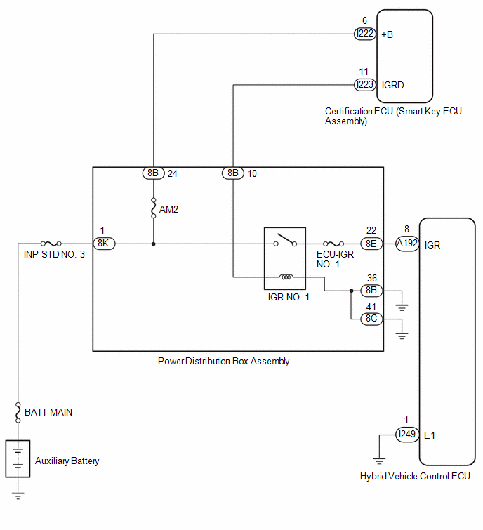
WIRING DIAGRAM
CAUTION / NOTICE / HINT
NOTICE:
Before replacing the certification ECU (smart key ECU assembly), refer to Registration.
Click here
PROCEDURE
|
1. | READ VALUE USING GTS (IGR) |
(a) Read the Data List.
Powertrain > Hybrid Control > Data List|
Tester Display |
|---|
|
IGR |
Standard:
|
GTS Display | Switch Condition |
Specified Condition |
|---|---|---|
| IGR |
Ignition switch ON | ON |
| OK | .gif) | CHECK FOR INTERMITTENT PROBLEMS |
|
.gif)
|
2. | CHECK TERMINAL VOLTAGE (IGR VOLTAGE) |
(a) Turn the ignition switch to ON.
(b) Measure the voltage according to the value(s) in the table below.
|
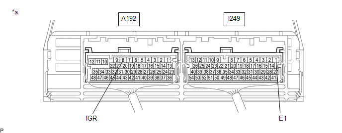
*a | Component with harness connected (Hybrid Vehicle Control ECU) |
- | - |
Standard Voltage:
|
Tester Connection | Switch Condition |
Specified Condition |
|---|---|---|
|
A192-8 (IGR) - I249-1 (E1) |
Ignition switch ON |
11 to 14 V |
(c) Turn the ignition switch off.
| OK | | REPLACE HYBRID VEHICLE CONTROL ECU |
|
|
3. | CHECK HARNESS AND CONNECTOR (POWER DISTRIBUTION BOX ASSEMBLY - HYBRID VEHICLE CONTROL ECU) |
(a) Disconnect the hybrid vehicle control ECU connector.
(b) Disconnect the power distribution box assembly connector.
(c) Measure the resistance according to the value(s) in the table below.
Standard Resistance (Check for Open):
|
Tester Connection | Condition |
Specified Condition |
|---|---|---|
|
8E-22 - A192-8 (IGR) |
Always | Below 1 Ω |
Standard Resistance (Check for Short):
|
Tester Connection | Condition |
Specified Condition |
|---|---|---|
|
8E-22 or A192-8 (IGR) - Other terminals and body ground |
Always | 10 kΩ or higher |
(d) Reconnect the power distribution box assembly connector.
(e) Reconnect the hybrid vehicle control ECU connector.
| NG | | REPAIR OR REPLACE HARNESS OR CONNECTOR |
|
|
4. | CHECK HARNESS AND CONNECTOR (POWER DISTRIBUTION BOX ASSEMBLY - BODY GROUND) |
(a) Disconnect the power distribution box assembly connectors.
(b) Measure the resistance according to the value(s) in the table below.
Standard Resistance:
|
Tester Connection | Condition |
Specified Condition |
|---|---|---|
|
8B-36 - Body ground |
Always | Below 1 Ω |
|
8C-41 - Body ground |
Always | Below 1 Ω |
(c) Reconnect the power distribution box assembly connectors.
| OK | | REPLACE POWER DISTRIBUTION BOX ASSEMBLY |
| NG | | REPAIR OR REPLACE HARNESS OR CONNECTOR |
READ NEXT:
 Lost Communication with Airbag System Control Module Circuit Short to Ground (P310711)
DESCRIPTION The hybrid vehicle control ECU detects a problem in the collision signal line from the airbag ECU assembly and alerts the driver.
DTC No. Detection Item
DTC Detection Condit
Lost Communication with Airbag System Control Module Circuit Short to Auxiliary Battery or Open (P310715)
DESCRIPTION Refer to the description for DTC P310711.
Click here
DTC No. Detection Item
DTC Detection Condition
Trouble Area MIL
Warning Indicate Note
P310
Lost Communication with Airbag System Control Module Signal Plausibility Failure (P310764)
DESCRIPTION Refer to the description for DTC P310711.
Click here
DTC No. Detection Item
DTC Detection Condition
Trouble Area MIL
Warning Indicate Note
P310
SEE MORE:
 Pressure Control Solenoid "B" Circuit Short to Ground or Open (P077514)
DESCRIPTION
Refer to DTC P077512.
Click here
DTC No.
Detection Item
DTC Detection Condition
Trouble Area
MIL
Memory
Note
P077514
Pressure Control Solenoid "B" Circuit Short to Grou
Fuel Pump Control (All Phase) Circuit Open (P12D013-P12D313)
DESCRIPTION Refer to DTC P062712. Click here
DTC No. Detection Item
DTC Detection Condition Trouble Area
MIL Note
P12D013 Fuel Pump Control (All Phase) Circuit Open
When the fuel pump control ECU operation duty ratio is 3 to 65%, an open is detected in the F
