Toyota Corolla Cross: Hybrid/EV Battery Voltage High (P31B300)
DTC SUMMARY
MALFUNCTION DESCRIPTION
The hybrid vehicle control ECU uses the inverter voltage to monitor the HV battery voltage and detect malfunctions.
The cause of this malfunction may be the following:
Inverter with converter assembly malfunction (Boost converter system)- VL sensor malfunction
- VH sensor malfunction
- Battery ECU assembly malfunction
- HV battery malfunction
DESCRIPTION
The hybrid vehicle control ECU uses the inverter voltage to monitor the HV battery voltage and detect malfunctions.
|
DTC No. | Detection Item |
DTC Detection Condition |
Trouble Area | MIL |
Warning Indicate | Note |
|---|---|---|---|---|---|---|
|
P31B300 | Hybrid/EV Battery Voltage High |
The inverter voltage exceeds the threshold. (1 trip detection logic) |
| Comes on |
Master Warning Light: Comes on |
SAE Code: P31B3 |
MONITOR DESCRIPTION
The hybrid vehicle control ECU monitors the cell overcharge signal. If the hybrid vehicle control ECU detects an abnormality in the sensor signal, the hybrid vehicle control ECU will illuminate the MIL and set a DTC.
MONITOR STRATEGY
|
Related DTCs | P31B3 (INF P31B300): Hybrid/EV Battery Voltage high |
|
Required sensors/components | Battery ECU assembly |
|
Frequency of operation | Continuous |
|
Duration | TMC's intellectual property |
|
MIL operation | 1 driving cycle |
|
Sequence of operation | None |
TYPICAL ENABLING CONDITIONS
|
The monitor will run whenever the following DTCs are not stored |
TMC's intellectual property |
|
Other conditions belong to TMC's intellectual property |
- |
TYPICAL MALFUNCTION THRESHOLDS
|
TMC's intellectual property | - |
COMPONENT OPERATING RANGE
|
Hybrid vehicle control ECU | P31B3 (INF P31B300) is not detected |
CONFIRMATION DRIVING PATTERN
HINT:
- After repair has been completed, clear the DTC and then check that the vehicle has returned to normal by performing the following All Readiness check procedure.
Click here
.gif)
- When clearing the permanent DTCs, refer to the "CLEAR PERMANENT DTC" procedure.
Click here
- Connect the GTS to the DLC3.
- Turn the ignition switch to ON and turn the GTS on.
- Clear the DTCs (even if no DTCs are stored, perform the clear DTC procedure).
- Turn the ignition switch off and wait for 2 minutes or more.
- Turn the ignition switch to ON and turn the GTS on.
- Turn the ignition switch to ON (READY) and wait for 30 seconds or more. [*1]
HINT:
[*1] : Normal judgment procedure.
The normal judgment procedure is used to complete DTC judgment and also used when clearing permanent DTCs.
- Enter the following menus: Powertrain / Hybrid Control / Utility / All Readiness.
- Check the DTC judgment result.
HINT:
- If the judgment result shows NORMAL, the system is normal.
- If the judgment result shows ABNORMAL, the system has a malfunction.
- If the judgment result shows INCOMPLETE, perform the normal judgment procedure again.
WIRING DIAGRAM
Refer to the wiring diagram for the HV battery high-voltage line circuit.
Click here
CAUTION / NOTICE / HINT
CAUTION:
Refer to the precautions before inspecting high voltage circuit.
Click here
NOTICE:
- After the ignition switch is turned off, there may be a waiting time before disconnecting the negative (-) auxiliary battery terminal.
Click here
- When disconnecting and reconnecting the auxiliary battery
HINT:
When disconnecting and reconnecting the auxiliary battery, there is an automatic learning function that completes learning when the respective system is used.
Click here
HINT:
- P31B300 may be output as a result of the malfunction indicated by the DTCs in table below.
- The chart above is listed in inspection order of priority.
- Check DTCs that are output at the same time by following the listed order. (The main cause of the malfunction can be determined without performing unnecessary inspections.)
|
Malfunction Content | System |
Relevant DTC | |
|---|---|---|---|
|
Sensor and actuator circuit malfunction |
Hybrid control system | P0D2D1C |
Drive Motor "A" Inverter Voltage Sensor Voltage Out of Range |
|
P0E311C | Boosting Converter Voltage Sensor "A" Voltage Out of Range | ||
|
P1C2D62 | Hybrid/EV Battery "A" Voltage Sensor/Boosting Converter Voltage Sensor "A" Signal Compare Failure | ||
|
Motor generator control system | P0D2D16 |
Drive Motor "A" Inverter Voltage Sensor (VH) Circuit Voltage Below Threshold | |
|
P0D2D17 | Drive Motor "A" Inverter Voltage Sensor (VH) Circuit Voltage Above Threshold | ||
|
P0D2D1F | Drive Motor "A" Inverter Voltage Sensor(VH) Circuit Intermittent | ||
|
P0E3116 | DC/DC Converter Voltage Sensor "A" (VL) Circuit Voltage Below Threshold | ||
|
P0E3117 | DC/DC Converter Voltage Sensor "A" (VL) Circuit Voltage Above Threshold | ||
|
P0E311F | DC/DC Converter Voltage Sensor "A"(VL) Circuit Intermittent | ||
|
P0E5717 | DC/DC Converter Voltage Sensor "A"(VL) Circuit Voltage Above Threshold | ||
PROCEDURE
|
1. | READ VALUE USING GTS (HYBRID/EV BATTERY VOLTAGE) |
(a) Read the Data List.
Powertrain > HV Battery > Data List|
Tester Display |
|---|
|
Hybrid/EV Battery Voltage |
NOTICE:
Be sure not to measure when the ignition switch is ON (READY).
(b) Make a note of the data list item "Hybrid/EV Battery Voltage".
(c) Turn the ignition switch off.
|
.gif)
|
2. | CHECK HV BATTERY |
CAUTION:
Be sure to wear insulated gloves.
(a) Check that the service plug grip is not installed.
NOTICE:
After removing the service plug grip, do not turn the ignition switch to ON (READY), unless instructed by the repair manual because this may cause a malfunction.
| (b) Disconnect the HV battery high voltage connectors. NOTICE: Insulate each disconnected high-voltage connector with insulating tape. Wrap the connector from the wire harness side to the end of the connector. |
|
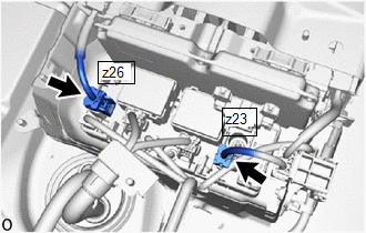
(c) Measure the voltage according to the value(s) in the table below.
Standard Voltage:
|
Tester Connection | Condition |
|---|---|
|
z26-1 (+) - z23-1 (-) |
Ignition switch off |
CAUTION:
Do not allow the probes of the electrical tester to contact each other during this inspection.
(d) Check the value in the data list "Hybrid/EV Battery Voltage" and the hybrid battery voltage value that was actually measured.
|
Result | Proceed to |
|---|---|
|
When the difference between "Hybrid/EV Battery Voltage" in the Data List and the measurement value of the HV battery voltage is 5 V or more. |
A |
| Other than above |
B |
(e) Reconnect the HV battery high voltage connectors.
| B | .gif) | GO TO STEP 4 |
|
|
3. | REPLACE BATTERY ECU ASSEMBLY |
Click here
| NEXT | | REPLACE HV BATTERY |
|
4. | CHECK FREEZE FRAME DATA (HYBRID/EV BATTERY VOLTAGE) |
(a) Read the freeze frame data of DTC P31B300.
Powertrain > Hybrid Control > DTC(P31B300) > Freeze Frame Data|
Tester Display |
|---|
|
Hybrid/EV Battery Voltage |
|
Result | Proceed to |
|---|---|
|
"Hybrid/EV Battery Voltage" is less than 292 V. |
A |
| Other than above |
B |
(b) Turn the ignition switch off.
| A | | REPLACE INVERTER WITH CONVERTER ASSEMBLY |
|
|
5. | REPLACE BATTERY ECU ASSEMBLY |
Click here
| NEXT | | REPLACE HV BATTERY |


