Toyota Corolla Cross: Hybrid/EV Battery Energy Control Module Hybrid/EV Battery Monitor Performance (P0E2D00)
DESCRIPTION
The battery ECU assembly detects the voltage of each HV battery cell. The battery ECU assembly monitors its internal HV battery cell voltage detection circuits to detect malfunctions. If the battery ECU assembly detects a malfunction it will store this DTC.
HINT:
If this DTC is output, it will be necessary to replace the battery ECU assembly.
|
DTC No. | Detection Item |
DTC Detection Condition |
Trouble Area | MIL |
Warning Indicate | Note |
|---|---|---|---|---|---|---|
|
P0E2D00 | Hybrid/EV Battery Energy Control Module Hybrid/EV Battery Monitor Performance |
The battery ECU assembly detects a malfunction of its internal HV battery cell voltage detection circuits. (1 trip detection logic) |
| Comes on |
Master Warning: Comes on |
SAE Code: P0E2D |
MONITOR DESCRIPTION
The battery ECU assembly monitors its internal HV battery cell voltage detection circuits to detect malfunctions. If the battery ECU assembly detects a malfunction, it will illuminate the MIL and store a DTC.
MONITOR STRATEGY
|
Related DTCs | P0E2D (INF P0E2D00): Internal control module hybrid/EV battery monitor performance |
|
Required sensors/components | Battery ECU assembly |
|
Frequency of operation | Continuous |
|
Duration | TMC's intellectual property |
|
MIL operation | 1 driving cycle |
|
Sequence of operation | None |
TYPICAL ENABLING CONDITIONS
|
The monitor will run whenever the following DTCs are not stored |
TMC's intellectual property |
|
Other conditions belong to TMC's intellectual property |
- |
TYPICAL MALFUNCTION THRESHOLDS
|
TMC's intellectual property | - |
COMPONENT OPERATING RANGE
|
Battery ECU assembly | DTC P0E2D (INF P0E2D00) is not detected |
CONFIRMATION DRIVING PATTERN
HINT:
- After repair has been completed, clear the DTC and then check that the vehicle has returned to normal by performing the following All Readiness check procedure.
Click here
.gif)
- When clearing the permanent DTCs, refer to the "CLEAR PERMANENT DTC" procedure.
Click here
- Connect the GTS to the DLC3.
- Turn the ignition switch to ON and turn the GTS on.
- Clear the DTCs (even if no DTCs are stored, perform the clear DTC procedure).
- Turn the ignition switch off and wait for 2 minutes or more.
- Turn the ignition switch to ON and turn the GTS on.
- With the vehicle stopped and the shift position in P, turn the ignition switch to ON and wait for at least 70 seconds. [*1]
- Turn the ignition switch to ON (READY) and without depressing the accelerator pedal, and while depressing the brake pedal, change the shift position to D and wait for 1 minute. (Step A)[*2]
- Drive the vehicle 0.5 m (1.6 ft.) forward and perform step A.[*3]
- Drive the vehicle another 0.5 m (1.6 ft.) forward and perform step A. Repeat this procedure 5 times (minimum total driving distance: 2 m (6.6 ft.)).[*4]
HINT:
[*1] to [*4]: Normal judgment procedure.
The normal judgment procedure is used to complete DTC judgment and also used when clearing permanent DTCs.
- Enter the following menus: Powertrain / HV Battery / Utility / All Readiness.
- Check the DTC judgment result.
HINT:
- If the judgment result shows NORMAL, the system is normal.
- If the judgment result shows ABNORMAL, the system has a malfunction.
- If the judgment result shows INCOMPLETE, perform the normal judgment procedure again.
WIRING DIAGRAM
Refer to the wiring diagram for DTC P1A001C.
Click here
CAUTION / NOTICE / HINT
CAUTION:
Refer to the precautions before inspecting high voltage circuit.
Click here
NOTICE:
- After the ignition switch is turned off, there may be a waiting time before disconnecting the negative (-) auxiliary battery terminal.
Click here
- When disconnecting and reconnecting the auxiliary battery
HINT:
When disconnecting and reconnecting the auxiliary battery, there is an automatic learning function that completes learning when the respective system is used.
Click here
PROCEDURE
|
1. | CHECK DTC OUTPUT (HV BATTERY, HYBRID CONTROL) |
(a) Check for DTCs.
Powertrain > HV Battery > Trouble Codes Powertrain > Hybrid Control > Trouble Codes|
Result | Proceed to |
|---|---|
|
"P0E2D00" only is output, or DTCs except the ones in the table below are also output. |
A |
| DTCs of hybrid battery system in the table below are output. |
B |
| DTCs of hybrid control system in the table below are output. |
C |
|
System | Relevant DTC | |
|---|---|---|
|
Hybrid battery system |
P060A47 | Hybrid/EV Battery Energy Control Module Monitoring Processor Watchdog / Safety MCU Failure |
|
P060B49 | Hybrid/EV Battery Energy Control Module A/D Processing Internal Electronic Failure | |
|
P060687 | Hybrid/EV Battery Energy Control Module Processor to Monitoring Processor Missing Message | |
|
P1A001C | Hybrid Battery Stack 2 Cell Voltage Detection Voltage Out of Range | |
|
P301A1C | Hybrid Battery Stack 1 Cell Voltage Detection Voltage Out of Range | |
|
Hybrid control system |
P0A1F94 | Hybrid/EV Battery Energy Control Module Unexpected Operation |
(b) Turn the ignition switch off.
| B | .gif) | GO TO DTC CHART (HYBRID BATTERY SYSTEM) |
| C | | GO TO DTC CHART (HYBRID CONTROL SYSTEM) |
|
.gif)
|
2. | CHECK CONNECTOR CONNECTION CONDITION (BATTERY ECU ASSEMBLY CONNECTOR) |
CAUTION:
Be sure to wear insulated gloves and protective goggles.
(a) Check that the service plug grip is not installed.
NOTICE:
After removing the service plug grip, do not turn the ignition switch to ON (READY), unless instructed by the repair manual because this may cause a malfunction.
| (b) Check the connector connections and contact pressure of the relevant terminals for the battery ECU assembly. Click here OK: The connectors are connected securely and there are no contact problems. Result:
|
| |||||||||||||
.png)
| B | | CONNECT SECURELY |
| C | | REPLACE HV BATTERY |
|
|
3. | READ VALUE USING GTS (HYBRID/EV BATTERY CELL VOLTAGE) |
(a) Read the Data List.
Powertrain > HV Battery > Data List|
Tester Display |
|---|
|
Hybrid/EV Battery Cell 1 Voltage |
|
Hybrid/EV Battery Cell 2 Voltage |
|
Hybrid/EV Battery Cell 3 Voltage |
|
Hybrid/EV Battery Cell 4 Voltage |
|
Hybrid/EV Battery Cell 5 Voltage |
|
Hybrid/EV Battery Cell 6 Voltage |
|
Hybrid/EV Battery Cell 7 Voltage |
|
Hybrid/EV Battery Cell 8 Voltage |
|
Hybrid/EV Battery Cell 9 Voltage |
|
Hybrid/EV Battery Cell 10 Voltage |
|
Hybrid/EV Battery Cell 11 Voltage |
|
Hybrid/EV Battery Cell 12 Voltage |
|
Hybrid/EV Battery Cell 13 Voltage |
|
Hybrid/EV Battery Cell 14 Voltage |
|
Hybrid/EV Battery Cell 15 Voltage |
|
Hybrid/EV Battery Cell 16 Voltage |
|
Hybrid/EV Battery Cell 17 Voltage |
|
Hybrid/EV Battery Cell 18 Voltage |
|
Hybrid/EV Battery Cell 19 Voltage |
|
Hybrid/EV Battery Cell 20 Voltage |
|
Hybrid/EV Battery Cell 21 Voltage |
|
Hybrid/EV Battery Cell 22 Voltage |
|
Hybrid/EV Battery Cell 23 Voltage |
|
Hybrid/EV Battery Cell 24 Voltage |
|
Hybrid/EV Battery Cell 25 Voltage |
|
Hybrid/EV Battery Cell 26 Voltage |
|
Hybrid/EV Battery Cell 27 Voltage |
|
Hybrid/EV Battery Cell 28 Voltage |
|
Hybrid/EV Battery Cell 29 Voltage |
|
Hybrid/EV Battery Cell 30 Voltage |
|
Hybrid/EV Battery Cell 31 Voltage |
|
Hybrid/EV Battery Cell 32 Voltage |
|
Hybrid/EV Battery Cell 33 Voltage |
|
Hybrid/EV Battery Cell 34 Voltage |
|
Hybrid/EV Battery Cell 35 Voltage |
|
Hybrid/EV Battery Cell 36 Voltage |
|
Hybrid/EV Battery Cell 37 Voltage |
|
Hybrid/EV Battery Cell 38 Voltage |
|
Hybrid/EV Battery Cell 39 Voltage |
|
Hybrid/EV Battery Cell 40 Voltage |
|
Hybrid/EV Battery Cell 41 Voltage |
|
Hybrid/EV Battery Cell 42 Voltage |
|
Hybrid/EV Battery Cell 43 Voltage |
|
Hybrid/EV Battery Cell 44 Voltage |
|
Hybrid/EV Battery Cell 45 Voltage |
|
Hybrid/EV Battery Cell 46 Voltage |
|
Hybrid/EV Battery Cell 47 Voltage |
|
Hybrid/EV Battery Cell 48 Voltage |
|
Hybrid/EV Battery Cell 49 Voltage |
|
Hybrid/EV Battery Cell 50 Voltage |
|
Hybrid/EV Battery Cell 51 Voltage |
|
Hybrid/EV Battery Cell 52 Voltage |
|
Hybrid/EV Battery Cell 53 Voltage |
|
Hybrid/EV Battery Cell 54 Voltage |
|
Hybrid/EV Battery Cell 55 Voltage |
|
Hybrid/EV Battery Cell 56 Voltage |
|
Hybrid/EV Battery Cell 57 Voltage |
|
Hybrid/EV Battery Cell 58 Voltage |
|
Hybrid/EV Battery Cell 59 Voltage |
|
Hybrid/EV Battery Cell 60 Voltage |
|
Result | Proceed to |
|---|---|
|
There are two or more HV battery cell of 1.6 V or less in the data list item "Hybrid/EV Battery Cell 1 to 60 Voltage" |
A |
| Other than above |
B |
(b) Turn the ignition switch off.
| B | | GO TO STEP 5 |
|
|
4. | REPLACE BATTERY ECU ASSEMBLY |
Click here
| NEXT | | REPLACE HV BATTERY |
|
5. | CHECK FREEZE FRAME DATA (HYBRID/EV BATTERY CELL VOLTAGE) |
(a) Read the value of freeze frame data items "Hybrid/EV Battery Cell 1 Voltage" through "Hybrid/EV Battery Cell 60 Voltage" for DTC P0E2D00 and make a note if the value of any is 1.6 V or less.
Powertrain > HV Battery > Trouble Codes|
Result | Proceed to |
|---|---|
|
The value of any of the freeze frame data items "Hybrid/EV Battery Cell 1 Voltage" through "Hybrid/EV Battery Cell 30 Voltage" is 1.6 V or less. |
A |
| The value of any of the freeze frame data items "Hybrid/EV Battery Cell 31 Voltage" through "Hybrid/EV Battery Cell 60 Voltage" is 1.6 V or less. |
B |
| Other than above |
C |
(b) Turn the ignition switch off.
| B | | GO TO STEP 9 |
| C | | REPLACE BATTERY ECU ASSEMBLY |
|
|
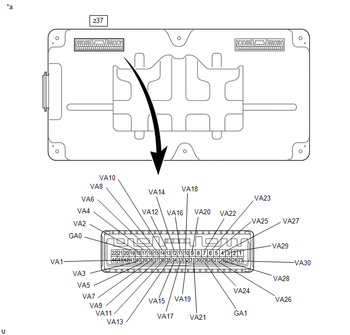
6. | CHECK HV BATTERY (HV BATTERY CELL VOLTAGE 1 - 30) |
CAUTION:
- Be sure to wear insulated gloves and protective goggles.
- Disconnect only the connector corresponding to the HV battery cell to be checked. Do not disconnect the other connectors.
NOTICE:
Make sure to use tester probes with a diameter of approximately 0.5 mm (0.0197 in.) when measuring the voltage of each HV battery cell.
(a) Check that the service plug grip is not installed.
NOTICE:
After removing the service plug grip, do not turn the ignition switch to ON (READY), unless instructed by the repair manual because this may cause a malfunction.
| (b) Disconnect the battery ECU assembly connector. |
|
.png)
(c) Measure the voltage according to the value(s) in the table below.
HINT:
Measure the voltage of the HV battery cells whose value in the freeze frame data was 1.6 V or less only.
|
HV Battery Cell | Tester Connection |
Condition |
|---|---|---|
|
1 | z37-19 (GA0) - z37-41 (VA1) |
Always |
|
2 | z37-41 (VA1) - z37-18 (VA2) |
Always |
|
3 | z37-18 (VA2) - z37-40 (VA3) |
Always |
|
4 | z37-40 (VA3) - z37-17 (VA4) |
Always |
|
5 | z37-17 (VA4) - z37-39 (VA5) |
Always |
|
6 | z37-39 (VA5) - z37-16 (VA6) |
Always |
|
7 | z37-16 (VA6) - z37-38 (VA7) |
Always |
|
8 | z37-38 (VA7) - z37-15 (VA8) |
Always |
|
9 | z37-15 (VA8) - z37-37 (VA9) |
Always |
|
10 | z37-37 (VA9) - z37-14 (VA10) |
Always |
|
11 | z37-14 (VA10) - z37-36 (VA11) |
Always |
|
12 | z37-36 (VA11) - z37-13 (VA12) |
Always |
|
13 | z37-13 (VA12) - z37-35 (VA13) |
Always |
|
14 | z37-35 (VA13) - z37-12 (VA14) |
Always |
|
15 | z37-12 (VA14) - z37-34 (VA15) |
Always |
|
16 | z37-34 (VA15) - z37-11 (VA16) |
Always |
|
17 | z37-11 (VA16) - z37-33 (VA17) |
Always |
|
18 | z37-33 (VA17) - z37-10 (VA18) |
Always |
|
19 | z37-10 (VA18) - z37-32 (VA19) |
Always |
|
20 | z37-32 (VA19) - z37-9 (VA20) |
Always |
|
21 | z37-9 (VA20) - z37-31 (VA21) |
Always |
|
22 | z37-31 (VA21) - z37-7 (VA22) |
Always |
|
23 | z37-29 (GA1) - z37-6 (VA23) |
Always |
|
24 | z37-6 (VA23) - z37-28 (VA24) |
Always |
|
25 | z37-28 (VA24) - z37-5 (VA25) |
Always |
|
26 | z37-5 (VA25) - z37-27 (VA26) |
Always |
|
27 | z37-27 (VA26) - z37-4 (VA27) |
Always |
|
28 | z37-4 (VA27) - z37-26 (VA28) |
Always |
|
29 | z37-26 (VA28) - z37-3 (VA29) |
Always |
|
30 | z37-3 (VA29) - z37-23 (VA30) |
Always |
CAUTION:
Make sure not to cross the electrodes of an electrical tester measurement terminals.
NOTICE:
Make sure to check the polarity of each terminal (positive (+) or negative (-)) before connecting a tester.
| Result |
Proceed to |
|---|---|
| The voltage between the terminals is 1.6 V or less. |
A |
| Other than above |
B |
(d) Reconnect the battery ECU assembly connector.
| B | | REPLACE BATTERY ECU ASSEMBLY |
|
|
7. | CHECK BATTERY ECU ASSEMBLY (GA0 - VA30) |
NOTICE:
Make sure to use tester probes with a diameter of approximately 0.5 mm (0.0197 in.) when measuring the resistance.
(a) Remove the battery ECU assembly.
Click here
(b) Measure the resistance according to the value(s) in the table below.
HINT:
Only inspect the terminals of the battery ECU assembly which correspond to the HV battery cells which measured 1.6 V or less in the previous step.
|
*a | Component without harness connected (Battery ECU Assembly) |
- | - |
Standard Resistance:
|
HV Battery Cell | Tester Connection (Tester Probe Polarity) |
Condition | Specified Condition |
|---|---|---|---|
|
1 | z37-19 (GA0) (-) - z37-41 (VA1) (+) |
Always | 50 kΩ or more |
|
2 | z37-41 (VA1) (-) - z37-18 (VA2) (+) |
Always | 50 kΩ or more |
|
3 | z37-18 (VA2) (-) - z37-40 (VA3) (+) |
Always | 50 kΩ or more |
|
4 | z37-40 (VA3) (-) - z37-17 (VA4) (+) |
Always | 50 kΩ or more |
|
5 | z37-17 (VA4) (-) - z37-39 (VA5) (+) |
Always | 50 kΩ or more |
|
6 | z37-39 (VA5) (-) - z37-16 (VA6) (+) |
Always | 50 kΩ or more |
|
7 | z37-16 (VA6) (-) - z37-38 (VA7) (+) |
Always | 50 kΩ or more |
|
8 | z37-38 (VA7) (-) - z37-15 (VA8) (+) |
Always | 50 kΩ or more |
|
9 | z37-15 (VA8) (-) - z37-37 (VA9) (+) |
Always | 50 kΩ or more |
|
10 | z37-37 (VA9) (-) - z37-14 (VA10) (+) |
Always | 50 kΩ or more |
|
11 | z37-14 (VA10) (-) - z37-36 (VA11) (+) |
Always | 50 kΩ or more |
|
12 | z37-36 (VA11) (-) - z37-13 (VA12) (+) |
Always | 50 kΩ or more |
|
13 | z37-13 (VA12) (-) - z37-35 (VA13) (+) |
Always | 50 kΩ or more |
|
14 | z37-35 (VA13) (-) - z37-12 (VA14) (+) |
Always | 50 kΩ or more |
|
15 | z37-12 (VA14) (-) - z37-34 (VA15) (+) |
Always | 50 kΩ or more |
|
16 | z37-34 (VA15) (-) - z37-11 (VA16) (+) |
Always | 50 kΩ or more |
|
17 | z37-11 (VA16) (-) - z37-33 (VA17) (+) |
Always | 50 kΩ or more |
|
18 | z37-33 (VA17) (-) - z37-10 (VA18) (+) |
Always | 50 kΩ or more |
|
19 | z37-10 (VA18) (-) - z37-32 (VA19) (+) |
Always | 50 kΩ or more |
|
20 | z37-32 (VA19) (-) - z37-9 (VA20) (+) |
Always | 50 kΩ or more |
|
21 | z37-9 (VA20) (-) - z37-31 (VA21) (+) |
Always | 50 kΩ or more |
|
22 | z37-31 (VA21) (-) - z37-7 (VA22) (+) |
Always | 50 kΩ or more |
|
23 | z37-29 (GA1) (-) - z37-6 (VA23) (+) |
Always | 50 kΩ or more |
|
24 | z37-6 (VA23) (-) - z37-28 (VA24) (+) |
Always | 50 kΩ or more |
|
25 | z37-28 (VA24) (-) - z37-5 (VA25) (+) |
Always | 50 kΩ or more |
|
26 | z37-5 (VA25) (-) - z37-27 (VA26) (+) |
Always | 50 kΩ or more |
|
27 | z37-27 (VA26) (-) - z37-4 (VA27) (+) |
Always | 50 kΩ or more |
|
28 | z37-4 (VA27) (-) - z37-26 (VA28) (+) |
Always | 50 kΩ or more |
|
29 | z37-26 (VA28) (-) - z37-3 (VA29) (+) |
Always | 50 kΩ or more |
|
30 | z37-3 (VA29) (-) - z37-23 (VA30) (+) |
Always | 50 kΩ or more |
NOTICE:
- Make sure to check the polarity of each terminal (positive (+) or negative (-)) before connecting a tester.
- Read the resistance after the value has stabilized.
- In order to avoid damaging the terminals of the battery ECU assembly, make sure to use tester probes with a diameter of approximately 0.5 mm (0.0197 in.) when measuring the resistance of the battery ECU assembly.
(c) Install the battery ECU assembly.
| Result |
Proceed to |
|---|---|
| The voltage between the terminals is 50 kΩ or more. |
A |
| Other than above |
B |
| A | | REPLACE HV BATTERY |
|
|
8. | REPLACE HV BATTERY |
Click here
| NEXT | | REPLACE BATTERY ECU ASSEMBLY |
|
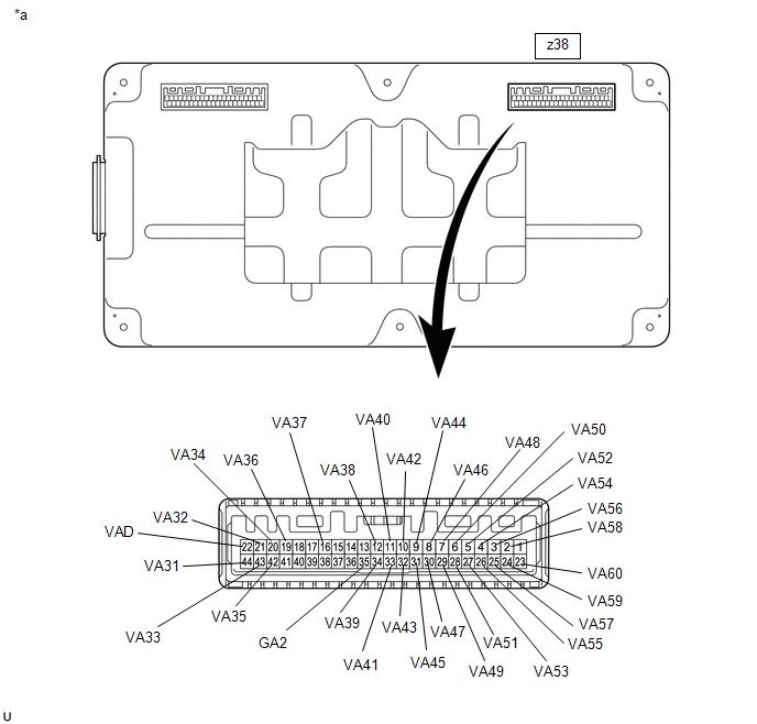
9. | CHECK HV BATTERY (HV BATTERY CELL VOLTAGE 31 - 60) |
CAUTION:
- Be sure to wear insulated gloves and protective goggles.
- Disconnect only the connector corresponding to the HV battery cell to be checked. Do not disconnect the other connectors.
NOTICE:
Make sure to use tester probes with a diameter of approximately 0.5 mm (0.0197 in.) when measuring the voltage of each HV battery cell.
(a) Check that the service plug grip is not installed.
NOTICE:
After removing the service plug grip, do not turn the ignition switch to ON (READY), unless instructed by the repair manual because this may cause a malfunction.
| (b) Disconnect the battery ECU assembly connector. |
|
.png)
(c) Measure the voltage according to the value(s) in the table below.
HINT:
Measure the voltage of the HV battery cells whose value in the freeze frame data was 1.6 V or less only.
|
HV Battery Cell | Tester Connection |
Condition |
|---|---|---|
|
31 | z38-22 (VAD) - z38-44 (VA31) |
Always |
|
32 | z38-44 (VA31) - z38-21 (VA32) |
Always |
|
33 | z38-21 (VA32) - z38-43 (VA33) |
Always |
|
34 | z38-43 (VA33) - z38-20 (VA34) |
Always |
|
35 | z38-20 (VA34) - z38-42 (VA35) |
Always |
|
36 | z38-42 (VA35) - z38-19 (VA36) |
Always |
|
37 | z38-19 (VA36) - z38-16 (VA37) |
Always |
|
38 | z38-35 (GA2) - z38-12 (VA38) |
Always |
|
39 | z38-12 (VA38) - z38-34 (VA39) |
Always |
|
40 | z38-34 (VA39) - z38-11 (VA40) |
Always |
|
41 | z38-11 (VA40) - z38-33 (VA41) |
Always |
|
42 | z38-33 (VA41) - z38-10 (VA42) |
Always |
|
43 | z38-10 (VA42) - z38-32 (VA43) |
Always |
|
44 | z38-32 (VA43) - z38-9 (VA44) |
Always |
|
45 | z38-9 (VA44) - z38-31 (VA45) |
Always |
|
46 | z38-31 (VA45) - z38-8 (VA46) |
Always |
|
47 | z38-8 (VA46) - z38-30 (VA47) |
Always |
|
48 | z38-30 (VA47) - z38-7 (VA48) |
Always |
|
49 | z38-7 (VA48) - z38-29 (VA49) |
Always |
|
50 | z38-29 (VA49) - z38-6 (VA50) |
Always |
|
51 | z38-6 (VA50) - z38-28 (VA51) |
Always |
|
52 | z38-28 (VA51) - z38-5 (VA52) |
Always |
|
53 | z38-5 (VA52) - z38-27 (VA53) |
Always |
|
54 | z38-27 (VA53) - z38-4 (VA54) |
Always |
|
55 | z38-4 (VA54) - z38-26 (VA55) |
Always |
|
56 | z38-26 (VA55) - z38-3 (VA56) |
Always |
|
57 | z38-3 (VA56) - z38-25 (VA57) |
Always |
|
58 | z38-25 (VA57) - z38-2 (VA58) |
Always |
|
59 | z38-2 (VA58) - z38-24 (VA59) |
Always |
|
60 | z38-24 (VA59) - z38-23 (VA60) |
Always |
CAUTION:
Make sure not to cross the electrodes of an electrical tester measurement terminals.
NOTICE:
Make sure to check the polarity of each terminal (positive (+) or negative (-)) before connecting a tester.
| Result |
Proceed to |
|---|---|
| The voltage between the terminals is 1.6 V or less. |
A |
| Other than above |
B |
(d) Reconnect the battery ECU assembly connector.
| B | | REPLACE BATTERY ECU ASSEMBLY |
|
|
10. | CHECK BATTERY ECU ASSEMBLY (VAD - VA60) |
NOTICE:
Make sure to use tester probes with a diameter of approximately 0.5 mm (0.0197 in.) when measuring the resistance.
(a) Remove the battery ECU assembly.
Click here
(b) Measure the resistance according to the value(s) in the table below.
HINT:
Only inspect the terminals of the battery ECU assembly which correspond to the HV battery cells which measured 1.6 V or less in the previous step.
|
*a | Component without harness connected (Battery ECU Assembly) |
- | - |
Standard Resistance:
|
HV Battery Cell | Tester Connection (Tester Probe Polarity) |
Condition | Specified Condition |
|---|---|---|---|
|
31 | z38-22 (VAD) (-) - z38-44 (VA31) (+) |
Always | 50 kΩ or more |
|
32 | z38-44 (VA31) (-) - z38-21 (VA32) (+) |
Always | 50 kΩ or more |
|
33 | z38-21 (VA32) (-) - z38-43 (VA33) (+) |
Always | 50 kΩ or more |
|
34 | z38-43 (VA33) (-) - z38-20 (VA34) (+) |
Always | 50 kΩ or more |
|
35 | z38-20 (VA34) (-) - z38-42 (VA35) (+) |
Always | 50 kΩ or more |
|
36 | z38-42 (VA35) (-) - z38-19 (VA36) (+) |
Always | 50 kΩ or more |
|
37 | z38-19 (VA36) (-) - z38-16 (VA37) (+) |
Always | 50 kΩ or more |
|
38 | z38-35 (GA2) (-) - z38-12 (VA38) (+) |
Always | 50 kΩ or more |
|
39 | z38-12 (VA38) (-) - z38-34 (VA39) (+) |
Always | 50 kΩ or more |
|
40 | z38-34 (VA39) (-) - z38-11 (VA40) (+) |
Always | 50 kΩ or more |
|
41 | z38-11 (VA40) (-) - z38-33 (VA41) (+) |
Always | 50 kΩ or more |
|
42 | z38-33 (VA41) (-) - z38-10 (VA42) (+) |
Always | 50 kΩ or more |
|
43 | z38-10 (VA42) (-) - z38-32 (VA43) (+) |
Always | 50 kΩ or more |
|
44 | z38-32 (VA43) (-) - z38-9 (VA44) (+) |
Always | 50 kΩ or more |
|
45 | z38-9 (VA44) (-) - z38-31 (VA45) (+) |
Always | 50 kΩ or more |
|
46 | z38-31 (VA45) (-) - z38-8 (VA46) (+) |
Always | 50 kΩ or more |
|
47 | z38-8 (VA46) (-) - z38-30 (VA47) (+) |
Always | 50 kΩ or more |
|
48 | z38-30 (VA47) (-) - z38-7 (VA48) (+) |
Always | 50 kΩ or more |
|
49 | z38-7 (VA48) (-) - z38-29 (VA49) (+) |
Always | 50 kΩ or more |
|
50 | z38-29 (VA49) (-) - z38-6 (VA50) (+) |
Always | 50 kΩ or more |
|
51 | z38-6 (VA50) (-) - z38-28 (VA51) (+) |
Always | 50 kΩ or more |
|
52 | z38-28 (VA51) (-) - z38-5 (VA52) (+) |
Always | 50 kΩ or more |
|
53 | z38-5 (VA52) (-) - z38-27 (VA53) (+) |
Always | 50 kΩ or more |
|
54 | z38-27 (VA53) (-) - z38-4 (VA54) (+) |
Always | 50 kΩ or more |
|
55 | z38-4 (VA54) (-) - z38-26 (VA55) (+) |
Always | 50 kΩ or more |
|
56 | z38-26 (VA55) (-) - z38-3 (VA56) (+) |
Always | 50 kΩ or more |
|
57 | z38-3 (VA56) (-) - z38-25 (VA57) (+) |
Always | 50 kΩ or more |
|
58 | z38-25 (VA57) (-) - z38-2 (VA58) (+) |
Always | 50 kΩ or more |
|
59 | z38-2 (VA58) (-) - z38-24 (VA59) (+) |
Always | 50 kΩ or more |
|
60 | z38-24 (VA59) (-) - z38-23 (VA60) (+) |
Always | 50 kΩ or more |
NOTICE:
- Make sure to check the polarity of each terminal (positive (+) or negative (-)) before connecting a tester.
- Read the resistance after the value has stabilized.
- In order to avoid damaging the terminals of the battery ECU assembly, make sure to use tester probes with a diameter of approximately 0.5 mm (0.0197 in.) when measuring the resistance of the battery ECU assembly.
(c) Install the battery ECU assembly.
| Result |
Proceed to |
|---|---|
| The voltage between the terminals is 50 kΩ or more. |
A |
| Other than above |
B |
| A | | REPLACE HV BATTERY |
|
|
11. | REPLACE HV BATTERY |
Click here
| NEXT | | REPLACE BATTERY ECU ASSEMBLY |
READ NEXT:
 Hybrid Battery Stack 2 Cell Voltage Detection Voltage Out of Range (P1A001C,P301A1C)
DESCRIPTION The HV battery is composed of 60 cells (3.7 V each) in series. The battery ECU assembly monitors the voltage of each HV battery cell to detect malfunctions of the HV battery.
DTC No
Hybrid/EV Battery Stack 2 Cell Circuit Voltage Above Threshold (P1A6017,P31AA17)
DESCRIPTION The HV battery is composed of 60 cells (3.7 V each) in series. The battery ECU assembly monitors the voltage of each HV battery cell to detect malfunctions of the HV battery.
DTC No
Hybrid/EV Battery Stack 2 Cell Circuit Voltage Below Threshold (P1A6116,P31AB16)
DESCRIPTION If the voltage of an HV battery cell is lower than the threshold for a certain amount of time, the battery ECU assembly will interpret this as a malfunction.
DTC No. Detection Ite
SEE MORE:
 Parts Location
PARTS LOCATION ILLUSTRATION
*A for Gasoline Model
*B w/ Washer Fluid Level Warning System
*1 ECM
*2 BRAKE MASTER CYLINDER RESERVOIR ASSEMBLY
- BRAKE FLUID LEVEL WARNING SWITCH
*3 LEVEL WARNING SWITCH ASSEMBLY
*4 BRAKE ACTUATOR ASSEMBLY
VEHICLE CONTROL HISTORY (RoB)
VEHICLE CONTROL HISTORY (RoB)
DESCRIPTION
Vehicle Control History is a function that captures and stores ECU data
when triggered by specific vehicle behavior.
It may be possible to determine the cause of the malfunction by checking
the vehicle history information and freeze frame data.
