Toyota Corolla Cross: Headlight LH Circuit (B243900,B243A00)
DESCRIPTION
The light control LED ECU supplies internally boosted voltage to the light control LED ECU so that the current supplied to the LED is always maintained at a constant value.
These DTCs are also output when the main body ECU (multiplex network body ECU) detects malfunctions while monitoring the applied voltage.
|
DTC No. | Detection Item |
DTC Detection Condition | Trouble Area |
|---|---|---|---|
|
B243900 | Headlight LH Circuit | Detection condition:
|
|
| B243A00 |
Headlight RH Circuit | Detection condition:
|
|
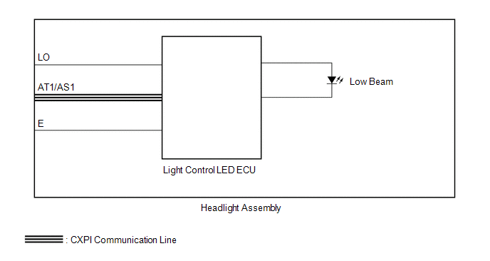
WIRING DIAGRAM
CAUTION / NOTICE / HINT
NOTICE:
- First perform the communication function inspections in How to Proceed with Troubleshooting to confirm that there are no CAN communication malfunctions before troubleshooting this symptom.
Click here
.gif)
- First perform the communication function inspections in How to Proceed with Troubleshooting to confirm that there are no CXPI communication malfunctions before troubleshooting this symptom.
Click here
PROCEDURE
|
1. | CLEAR DTC |
|
.gif)
| 2. |
CHECK FOR DTC |
(a) Check for DTCs.
Body Electrical > Main Body > Trouble CodesOK:
DTC B243900 and B243A00 are not output.
|
Result | Proceed to |
|---|---|
|
DTCs are not output | A |
|
B243900 is output | B |
|
B243A00 is output | C |
| A |
.gif) | USE SIMULATION METHOD TO CHECK |
| B |
| REPLACE HEADLIGHT ASSEMBLY LH
|
| C |
| REPLACE HEADLIGHT ASSEMBLY RH
|


