Toyota Corolla Cross: Headlight Dimmer Switch Circuit
DESCRIPTION
The steering sensor receives the following switch information:
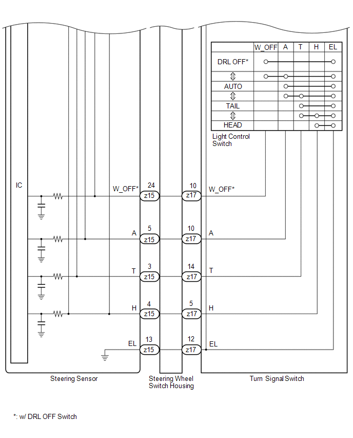
- Light control switch in DRL OFF*1, TAIL, HEAD, AUTO position
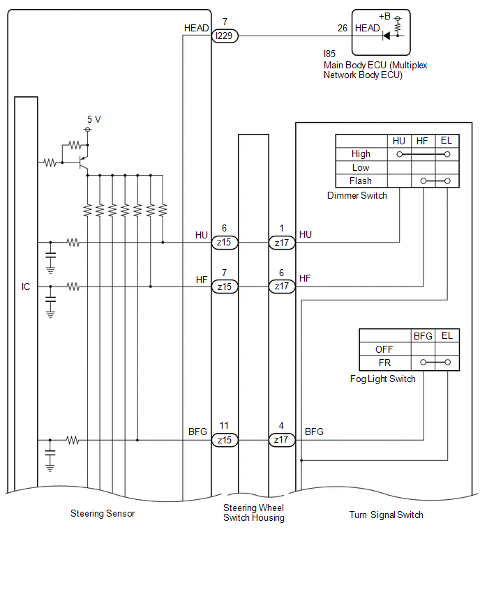
- Dimmer switch in high, low or high flash (pass) position
- Fog light switch in front*2 or off position
- *1: w/ DRL OFF Switch
- *2: w/ Fog Light
WIRING DIAGRAM
CAUTION / NOTICE / HINT
NOTICE:
Before replacing the main body ECU (multiplex network body ECU), refer to Registration.
PROCEDURE
| 1. |
READ VALUE USING GTS |
(a) Read the Data List according to the display on the GTS.
Chassis > Steering Angle Sensor > Data List|
Tester Display | Measurement Item |
Normal Condition | Reference Value |
Diagnostic Note |
|---|---|---|---|---|
|
Auto Light Switch | Light control switch AUTO position signal |
OFF or ON | OFF: Light control switch not in AUTO position ON: Light control switch in AUTO position |
- |
| Head Light Switch (Tail) |
Light control switch tail position signal |
OFF or ON | OFF: Light control switch not in tail position ON: Light control switch in tail position |
- |
| Head Light Switch (Head) |
Light control switch head position signal |
OFF or ON | OFF: Light control switch not in head position ON: Light control switch in head position |
- |
| High Beam Main Switch |
Dimmer switch high position signal |
OFF or ON | OFF: Dimmer switch not in high position ON: Dimmer switch in high position |
- |
| Passing Light Switch |
Dimmer switch high flash position (pass) signal |
OFF or ON | OFF: Dimmer switch not in high flash position ON: Dimmer switch in high flash position |
- |
| Front Fog Light Switch |
Front fog light switch signal |
OFF or ON | OFF: Front fog light switch off ON: Front fog light switch on |
- |
|
Tester Display |
|---|
| Auto Light Switch |
|
Head Light Switch (Tail) |
|
Head Light Switch (Head) |
|
High Beam Main Switch |
|
Passing Light Switch |
|
Front Fog Light Switch |
OK:
Normal conditions listed above are displayed.
| NG | .gif) | GO TO STEP 5 |
|
.gif)
| 2. |
READ VALUE USING GTS |
(a) Read the Data List according to the display on the GTS.
Body Electrical > Main Body > Data List|
Tester Display | Measurement Item |
Normal Condition | Reference Value |
Diagnostic Note |
|---|---|---|---|---|
|
Light Control Switch (HEAD) |
Light control switch head position signal |
OFF or ON | OFF: Light control switch not in head position ON: Light control switch in head position |
- |
|
Tester Display |
|---|
| Light Control Switch (HEAD) |
OK:
Normal conditions listed above are displayed.
| OK | | PROCEED TO NEXT SUSPECTED AREA SHOWN IN PROBLEM SYMPTOMS TABLE
|
|
| 3. |
INSPECT STEERING SENSOR |
|
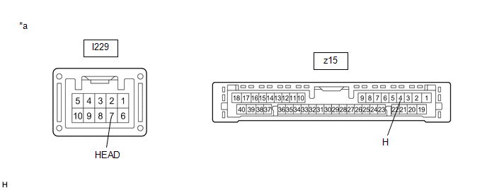
*a | Component without harness connected (Steering Sensor) | - |
- |
(a) Remove the steering sensor.
Click here .gif)
(b) Measure the resistance according to the value(s) in the table below.
Standard Resistance:
|
Tester Connection | Condition |
Specified Condition |
|---|---|---|
|
I229-7 (HEAD) - z15-4 (H) |
Always | Below 1 Ω |
| NG | | REPLACE STEERING SENSOR
|
|
| 4. |
CHECK HARNESS AND CONNECTOR (STEERING SENSOR - MAIN BODY ECU (MULTIPLEX NETWORK BODY ECU)) |
(a) Disconnect the I85 main body ECU (multiplex network body ECU) connector.
(b) Measure the resistance according to the value(s) in the table below.
Standard Resistance:
|
Tester Connection | Condition |
Specified Condition |
|---|---|---|
|
I229-7 (HEAD) - I85-26 (HEAD) |
Always | Below 1 Ω |
|
I229-7 (HEAD) - Body ground |
Always | 10 kΩ or higher |
|
I85-26 (HEAD) - Body ground |
Always | 10 kΩ or higher |
| OK | | REPLACE MAIN BODY ECU (MULTIPLEX NETWORK BODY ECU)
|
| NG | | REPAIR OR REPLACE HARNESS OR CONNECTOR |
| 5. |
INSPECT TURN SIGNAL SWITCH |
HINT:
Click here
| NG | | REPLACE TURN SIGNAL SWITCH |
|
| 6. |
INSPECT STEERING WHEEL SWITCH HOUSING |
HINT:
Click here
| OK | | REPLACE STEERING SENSOR
|
| NG | | REPLACE STEERING WHEEL SWITCH HOUSING
|


