Toyota Corolla Cross: Entry Exterior Alarm and Answer-back Buzzer do not Sound
DESCRIPTION
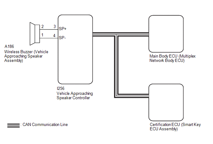
The smart key system (for Entry Function) uses the wireless buzzer to perform various vehicle exterior warnings. When the conditions of each warning are met, the certification ECU (smart key ECU assembly) sends a buzzer activation request signal to the main body ECU (multiplex network body ECU) via CAN communication and the buzzer sounds.
WIRING DIAGRAM
CAUTION / NOTICE / HINT
NOTICE:
- When using the GTS with the ignition switch off, connect the GTS to the DLC3 and turn a courtesy light switch on and off at intervals of 1.5 seconds or less until communication between the GTS and the vehicle begins. Then select the vehicle type under manual mode and enter the following menus: Body Electrical / Smart Key. While using the GTS, periodically turn a courtesy light switch on and off at intervals of 1.5 seconds or less to maintain communication between the GTS and the vehicle.
- The smart key system (for Entry Function) uses the CAN communication system. Inspect the communication function by following How to Proceed with Troubleshooting. Troubleshoot the smart key system (for Entry Function) after confirming that the communication systems are functioning properly.
Click here
.gif)
- Before replacing the certification ECU (smart key ECU assembly) or main body ECU (multiplex network body ECU), refer to Precaution.
Click here
- After repair, confirm that no DTCs are output.
PROCEDURE
|
1. | CHECK FOR DTC |
(a) Check for DTCs.
Body Electrical > Acoustic Vehicle Alerting System > Trouble Codes|
Result | Proceed to |
|---|---|
|
B135013 and B135019 are not output |
A |
| B135013 and B135019 are output |
B |
| B |
.gif) | GO TO ACOUSTIC VEHICLE ALERTING SYSTEM |
|
.gif)
| 2. |
CHECK CUSTOMIZE SETTING (WIRELESS BUZZER RESPONSE FUNCTION) |
(a) Read the customize setting according to the display on the GTS.
Wireless Door Lock|
Tester Display | Description |
Default | Setting |
ECU |
|---|---|---|---|---|
| Wireless Buzzer Response Function |
Wireless buzzer response |
Enable | $00:Disable,$01:Enable |
Main body ECU (multiplex network body ECU) |
|
Result | Proceed to |
|---|---|
|
"Enable" is displayed |
A |
| "Disable" is displayed |
B |
| B |
| PERFORM CUSTOMIZE SETTING |
|
| 3. |
CHECK WIRELESS DOOR LOCK CONTROL SYSTEM |
(a) Check that the function operates normally.
Click here
|
Result | Proceed to |
|---|---|
|
Wireless door lock function operates normally |
A |
| Wireless door lock function does not operate normally |
B |
| B |
| GO TO WIRELESS DOOR LOCK CONTROL SYSTEM |
|
| 4. |
READ VALUE USING GTS (EACH UNLOCK DETECTION SWITCH) |
(a) Read the Data List according to the display on the GTS.
Body Electrical > Main Body > Data List|
Tester Display | Measurement Item |
Range | Normal Condition |
Diagnostic Note |
|---|---|---|---|---|
|
FR Door Lock Position Switch Status |
Front door RH unlock detection switch signal |
Unlock or Lock | Unlock: Front door RH unlocked Lock: Front door RH locked |
- |
| FL Door Lock Position Switch Status |
Front door LH unlock detection switch signal |
Unlock or Lock | Unlock: Front door LH unlocked Lock: Front door LH locked |
- |
| RR Door Lock Position Switch Status |
Rear door RH unlock detection switch signal |
Unlock or Lock | Unlock: Rear door RH locked Lock: Rear door RH unlocked |
- |
| RL Door Lock Position Switch Status |
Rear door LH unlock detection switch signal |
Unlock or Lock | Unlock: Rear door LH locked Lock: Rear door LH unlocked |
- |
|
Tester Display |
|---|
| FR Door Lock Position Switch Status |
|
FL Door Lock Position Switch Status |
|
RR Door Lock Position Switch Status |
|
RL Door Lock Position Switch Status |
OK:
The GTS display changes correctly in response to the lock/unlock operation.
| OK | | REPLACE CERTIFICATION ECU (SMART KEY ECU ASSEMBLY) |
| NG | | GO TO LIGHTING SYSTEM (Proceed to Door Unlock Detection Switch Circuit) |


