Toyota Corolla Cross Owners & Service Manuals

Toyota Corolla Cross: Engine Switch

Removal

REMOVAL

CAUTION / NOTICE / HINT

COMPONENTS (REMOVAL)

Procedure

Part Name Code

1

AIR CONDITIONING CONTROL ASSEMBLY

55900

-

-

-

2

ENGINE SWITCH

89611

-

-

-

PROCEDURE

1. REMOVE AIR CONDITIONING CONTROL ASSEMBLY

Click here

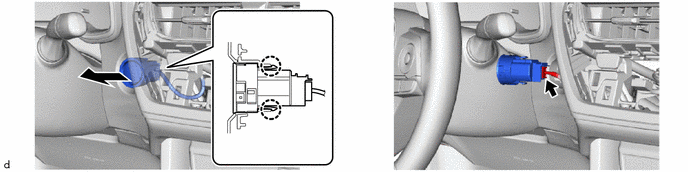
2. REMOVE ENGINE SWITCH

Inspection

INSPECTION

PROCEDURE

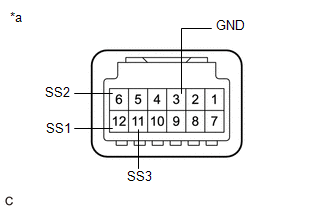
1. INSPECT ENGINE SWITCH

(a) Check the resistance.

(1) Measure the resistance according to the value(s) in the table below.

Standard Resistance:

Tester Connection

Switch Condition

Specified Condition

12 (SS1) - 3 (GND)

6 (SS2) - 3 (GND)

11 (SS3) - 3 (GND)

Not pushed

10 kΩ or higher

Pushed

Below 1 Ω

If the result is not as specified, replace the engine switch.

*a

Component without harness connected

(Engine Switch)

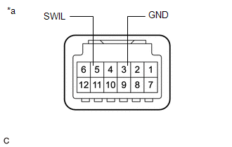
(b) Check the LED illumination.

(1) Apply battery voltage between the terminals of the engine switch and check the illumination condition of the engine switch indicator light.

OK:

Condition

Specified Condition

Battery positive (+) → Terminal 5 (SWIL)

Battery negative (-) → Terminal 3 (GND)

Illuminates

If the result is not as specified, replace the engine switch.

*a

Component without harness connected

(Engine Switch)

Installation

INSTALLATION

CAUTION / NOTICE / HINT

COMPONENTS (INSTALLATION)
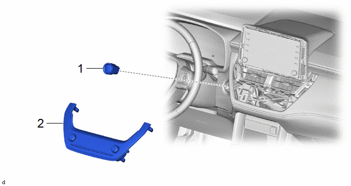
Procedure

Part Name Code

1

ENGINE SWITCH

89611

-

-

-

2

AIR CONDITIONING CONTROL ASSEMBLY

55900

-

-

-

PROCEDURE

1. INSTALL ENGINE SWITCH

2. INSTALL AIR CONDITIONING CONTROL ASSEMBLY

Click here

    READ NEXT:

     Ignition Switch

    RemovalREMOVAL CAUTION / NOTICE / HINT Procedure Part Name Code 1 LOWER STEERING COLUMN COVER 45287 - - 2 IGNITION OR STARTER SW

     Relay

    InspectionINSPECTION PROCEDURE 1. INSPECT STARTER RELAY ASSEMBLY (ST) (a) Check the resistance. (1) Measure the resistance according to the value(s) in the table below. Standard Resistance:

     Starter

    SEE MORE:

     Diagnosis System

    DIAGNOSIS SYSTEM DESCRIPTION When troubleshooting a vehicle with a diagnosis system, the only difference from the usual troubleshooting procedure is connecting the GTS to the vehicle and reading various data output from the engine stop and start ECU. The engine stop and start ECU records DTCs when

     Throttle/Pedal Position Sensor/Switch "D" Circuit Short to Auxiliary Battery (P212012,...,P21382B)

    DTC SUMMARY MALFUNCTION DESCRIPTION The hybrid vehicle control ECU calculates the accelerator pedal opening angle based on the output voltage of the main sensor (VPA) and sub sensor (VPA2) of the accelerator pedal (with sensor) rod assembly. If the output voltage of either the main sensor (VPA) or s

    © 2020-2025 Copyright www.tcorollacross.com PT