Toyota Corolla Cross: Engine Oil Temperature Sensor Circuit Short to Battery or Open (P019515)
DESCRIPTION
Refer to DTC P019511.
Click here
.gif)
|
DTC No. | Detection Item |
DTC Detection Condition | Trouble Area |
MIL | Note |
|---|---|---|---|---|---|
|
P019515 | Engine Oil Temperature Sensor Circuit Short to Battery or Open |
The oil pressure and temperature sensor output voltage is higher than 4.865 V for 5 seconds or more (1 trip detection logic). |
|
|
|
HINT:
When a DTC is output, check the Data List item "Engine Oil Temperature Sensor" using the GTS.
Click here
|
DTC No. | Engine Oil Temperature Sensor |
Malfunction |
|---|---|---|
| P019515 |
-40°C (-40°F) |
|
If the Data List displays a normal value, the normal value may be due to a temporary recovery from the malfunction condition. Check for intermittent problems.
MONITOR DESCRIPTION
The ECM monitors the oil pressure and temperature sensor and uses the sensor voltage to calculate the engine oil temperature. If the oil pressure and temperature sensor output voltage deviates from the normal operating range, the ECM determines that the oil pressure and temperature sensor circuit is malfunctioning and stores this DTC.
Example:
If the oil pressure and temperature sensor output voltage is higher than 4.865 V for 5 seconds or more, the ECM will store this DTC.
MONITOR STRATEGY
|
Related DTCs | P0198: Engine oil temperature sensor range check (high voltage) |
|
Required Sensors/Components (Main) | Engine oil temperature sensor |
|
Required Sensors/Components (Related) |
- |
| Frequency of Operation |
Continuous |
| Duration |
5 seconds |
| MIL Operation |
Immediate |
| Sequence of Operation |
None |
TYPICAL ENABLING CONDITIONS
|
All of the following conditions are met |
- |
| Auxiliary battery voltage |
8 V or higher |
| Ignition switch |
ON |
TYPICAL MALFUNCTION THRESHOLDS
|
Engine oil temperature sensor voltage | Higher than 4.865 V (156°C [312.8°F]) |
CONFIRMATION DRIVING PATTERN
HINT:
- After repair has been completed, clear the DTC and then check that the vehicle has returned to normal by performing the following All Readiness check procedure.
Click here
- When clearing the permanent DTCs, refer to the "CLEAR PERMANENT DTC" procedure.
Click here
- Connect the GTS to the DLC3.
- Turn the ignition switch to ON.
- Turn the GTS on.
- Clear the DTCs (even if no DTCs are stored, perform the clear DTC procedure).
- Turn the ignition switch off and wait for at least 30 seconds.
- Turn the ignition switch to ON [A].
- Turn the GTS on.
- Wait 10 seconds or more [B].
- Enter the following menus: Powertrain / Engine / Trouble Codes [C].
- Read the pending DTCs.
HINT:
- If a pending DTC is output, the system is malfunctioning.
- If a pending DTC is not output, perform the following procedure.
- Enter the following menus: Powertrain / Engine / Utility / All Readiness.
- Input the DTC: P019515.
- Check the DTC judgment result.
GTS Display
Description
NORMAL
- DTC judgment completed
- System normal
ABNORMAL
- DTC judgment completed
- System abnormal
INCOMPLETE
- DTC judgment not completed
- Perform driving pattern after confirming DTC enabling conditions
HINT:
- If the judgment result is NORMAL, the system is normal.
- If the judgment result is ABNORMAL, the system has a malfunction.
- If the judgment result is INCOMPLETE, perform steps [A] through [C] again.
- [A] to [C]: Normal judgment procedure.
The normal judgment procedure is used to complete DTC judgment and also used when clearing permanent DTCs.
- When clearing the permanent DTCs, do not disconnect the cable from the auxiliary battery terminal or attempt to clear the DTCs during this procedure, as doing so will clear the universal trip and normal judgment histories.
WIRING DIAGRAM
Refer to DTC P019511.
Click here
CAUTION / NOTICE / HINT
NOTICE:
- Vehicle Control History may be stored in the hybrid vehicle control ECU assembly if the engine is malfunctioning. Certain vehicle condition information is recorded when Vehicle Control History is stored. Reading the vehicle conditions recorded in both the freeze frame data and Vehicle Control History can be useful for troubleshooting.
Click here
(Select Powertrain in Health Check and then check the time stamp data.)
- If any "Engine Malfunction" Vehicle Control History item has been stored in the hybrid vehicle control ECU assembly, make sure to clear it. However, as all Vehicle Control History items are cleared simultaneously, if any Vehicle Control History items other than "Engine Malfunction" are stored, make sure to perform any troubleshooting for them before clearing Vehicle Control History.
Click here
HINT:
Read Freeze Frame Data using the GTS. The ECM records vehicle and driving condition information as Freeze Frame Data the moment a DTC is stored. When troubleshooting, Freeze Frame Data can help determine if the vehicle was moving or stationary, if the engine was warmed up or not, if the air fuel ratio was lean or rich, and other data from the time the malfunction occurred.
PROCEDURE
| 1. |
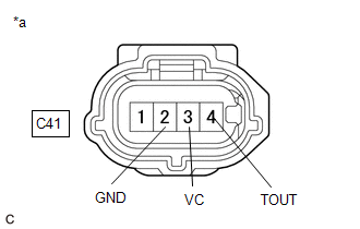
CHECK HARNESS AND CONNECTOR |
|
*a | Front view of wire harness connector (to Oil Pressure and Temperature Sensor) |
HINT:
Make sure that the connector is properly connected. If it is not, securely connect it and check for DTCs again.
(a) Disconnect the oil pressure and temperature sensor connector.
(b) Turn the ignition switch to ON.
(c) Measure the voltage according to the value(s) in the table below.
Standard Voltage:
|
Tester Connection | Switch Condition |
Specified Condition |
|---|---|---|
|
C41-3 (VC) - C41-2 (GND) |
Ignition switch ON | 4.5 to 5.5 V |
|
C41-4 (TOUT) - C41-2 (GND) |
Ignition switch ON | 3.0 to 5.5 V |
(d) Turn the ignition switch off and wait for at least 30 seconds.
(e) Measure the resistance according to the value(s) in the table below.
Standard Resistance:
|
Tester Connection | Switch Condition |
Specified Condition |
|---|---|---|
|
C41-2 (GND) - Body ground |
Ignition switch off | Below 1 Ω |
|
C41-3 (VC) - C41-4 (TOUT) |
Ignition switch off | 171 to 189 kΩ |
| OK | .gif) | REPLACE OIL PRESSURE AND TEMPERATURE SENSOR |
|
.gif)
| 2. |
CHECK HARNESS AND CONNECTOR (OIL PRESSURE AND TEMPERATURE SENSOR - ECM) |
(a) Disconnect the oil pressure and temperature sensor connector.
(b) Disconnect the ECM connector.
(c) Measure the resistance according to the value(s) in the table below.
Standard Resistance:
|
Tester Connection | Condition |
Specified Condition |
|---|---|---|
|
C41-2 (GND) - C139-100 (EPEO) |
Always | Below 1 Ω |
|
C41-4 (TOUT) - C139-123 (THEO) |
Always | Below 1 Ω |
|
C41-4 (TOUT) or C139-123 (THEO) - Other terminals |
Always | 10 kΩ or higher |
| OK | | REPLACE ECM |
| NG | | REPAIR OR REPLACE HARNESS OR CONNECTOR |
READ NEXT:
 Cylinder 1 Injector "A" Circuit Open (P020113-P020413,P062D13)
DESCRIPTION The D-4S system has two fuel injection systems. One is an in-cylinder direct injection system that directly injects pressurized fuel into the combustion chamber. The other is an intake por
Throttle/Pedal Position Sensor/Switch "B" Circuit Short to Ground (P022011)
DESCRIPTION Refer to DTC P012011. Click here
DTC No. Detection Item
DTC Detection Condition Trouble Area
MIL Note
P022011 Throttle/Pedal Position Sensor/Switch "B"
Throttle/Pedal Position Sensor/Switch "B" Circuit Short to Battery or Open (P022015)
DESCRIPTION Refer to DTC P012011. Click here
DTC No. Detection Item
DTC Detection Condition Trouble Area
MIL Note
P022015 Throttle/Pedal Position Sensor/Switch "B"
SEE MORE:
 Parts Location
PARTS LOCATION ILLUSTRATION
*1 FRONT DOOR COURTESY LIGHT SWITCH ASSEMBLY (LH)
*2 COMBINATION METER ASSEMBLY
*3 UN-LOCK WARNING SWITCH ASSEMBLY
*4 MAIN BODY ECU (MULTIPLEX NETWORK BODY ECU)
*5 POWER DISTRIBUTION BOX ASSEMBLY
*6 DLC3
Operation Check
OPERATION CHECK CHECK ELECTRICAL REMOTE CONTROL MIRROR FUNCTION
(a) Turn the ignition switch to ON. (b) With L on the mirror select and mirror adjust switch selected, check that the outer rear view mirror assembly LH surface moves up, down, left and right normally.
(c) With R on the mirror select
