Toyota Corolla Cross: Engine Oil Pressure Too Low (Severe) (P052477,P15F009,P15F077,P15F109,P15F177)
DESCRIPTION
Variable oil pump control uses the oil pressure control valve assembly, oil pressure and temperature sensor and ECM to optimize the oil pressure and oil volume required by each component to reduce friction by monitoring the engine temperature and engine speed.
The ECM drives the oil pressure control valve assembly based on the oil pressure measured by the oil pressure sensor. The oil pressure is controlled by operating the oil pressure control valve assembly to regulate the amount of discharge oil.
|
DTC No. | Detection Item |
DTC Detection Condition | Trouble Area |
MIL | Note |
|---|---|---|---|---|---|
|
P052477 | Engine Oil Pressure Too Low (Severe) |
When the engine is running, the oil pressure value output from the oil pressure and temperature sensor is less than the target value (1 trip detection logic). |
| Comes on |
|
| P15F009 |
Engine Oil Pressure Too Low (Moderate) |
When the engine is running, the oil pressure value output from the oil pressure and temperature sensor is less than the target value (1 trip detection logic). |
| Does not come on |
|
| P15F077 |
Engine Oil Pressure Too Low (Minor) |
When the engine is running, the oil pressure value output from the oil pressure and temperature sensor is less than the target value (1 trip detection logic). |
| Does not come on |
|
| P15F109 |
Variable Oil Pump Component Failure |
When the piston oil jets are spraying oil (engine speed is 3000 rpm or more), the oil pressure is less than specified (1 trip detection logic). |
| Does not come on |
|
| P15F177 |
Variable Oil Pump Commanded Position Not Reachable |
When the engine is running, the target value and the value output by the oil pressure sensor differ by more than the threshold (1 trip detection logic). |
| Does not come on |
|
|
DTC No. | Data List/Freeze Frame Data |
|---|---|
|
P052477 |
|
| P15F009 | |
|
P15F077 | |
| P15F109 | |
|
P15F177 |
MONITOR DESCRIPTION
P052477, P15F009, P15F077 and P15F177:The ECM monitors the oil pressure based on the signal output from the oil pressure and temperature sensor. If it is judged that the actual oil pressure generated by the oil pump assembly is less than the target oil pressure, oil pressure control using the oil pressure control valve assembly is suspended. After a certain period of time has elapsed, if it is judged that the actual oil pressure is low in comparison to the target oil pressure, it is determined that the oil pressure is low and a DTC is stored.
P15F109:The ECM monitors the oil pressure based on the signal output from the oil pressure and temperature sensor. If the oil pressure is less than specified when the piston oil jets are spraying oil (engine speed is 3000 rpm or more), a DTC is stored.
MONITOR STRATEGY
|
Related DTCs | P0524: Oil pressure control system (oil pressure low) |
|
Required Sensors/Components (Main) | Oil pressure sensor |
|
Required Sensors/Components (Related) | - |
|
Frequency of Operation | Once per driving cycle |
|
Duration | Less than 30 seconds |
|
MIL Operation | Immediate |
|
Sequence of Operation | None |
TYPICAL ENABLING CONDITIONS
P0524|
Monitor runs whenever the following DTCs are not stored |
None |
| Both of the following conditions are met |
- |
| Engine speed |
1500 rpm or higher |
| Engine coolant temperature |
0°C (32°F) or higher |
TYPICAL MALFUNCTION THRESHOLDS
P0524|
Engine oil pressure | Less than threshold value |
CONFIRMATION DRIVING PATTERN
HINT:
- After repair has been completed, clear the DTC and then check that the vehicle has returned to normal by performing the following All Readiness check procedure.
Click here
.gif)
- When clearing the permanent DTCs, refer to the "CLEAR PERMANENT DTC" procedure.
Click here
- Connect the GTS to the DLC3.
- Turn the ignition switch to ON.
- Turn the GTS on.
- Clear the DTCs (even if no DTCs are stored, perform the clear DTC procedure).
- Turn the ignition switch off and wait for at least 30 seconds.
- Turn the ignition switch to ON.
- Turn the GTS on.
- Put the engine in Inspection Mode (Maintenance Mode).
Click here
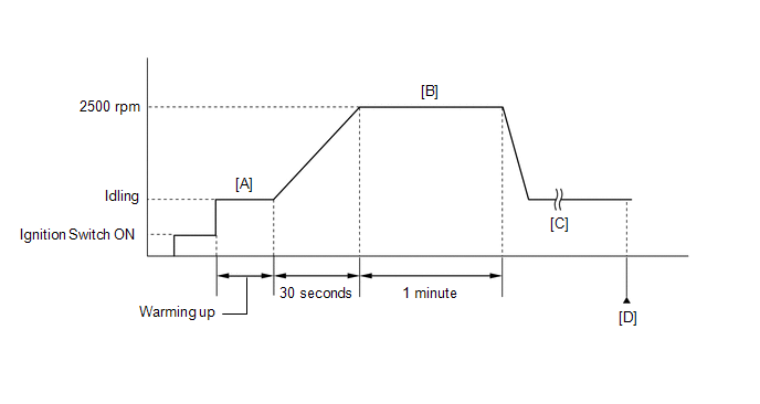
- Start the engine and warm it up until the engine coolant temperature is 75°C (167°F) or higher with all the accessories switched off [A].
- When the vehicle is stationery, gradually depress the accelerator pedal to increase the engine speed to 2500 rpm over a 30 second period, run the engine speed at 2500 rpm for 1 minute, then release the accelerator pedal to return to the idling speed [B].
- Repeat step [B] 3 times or more [C].
- Enter the following menus: Powertrain / Engine / Trouble Codes [D].
- Read the pending DTCs.
HINT:
- If a pending DTC is output, the system is malfunctioning.
- If a pending DTC is not output, perform the following procedure.
- Enter the following menus: Powertrain / Engine / Utility / All Readiness.
- Input the DTC: P052477, P15F009, P15F077, P15F109 or P15F177.
- Check the DTC judgment result.
GTS Display
Description
NORMAL
- DTC judgment completed
- System normal
ABNORMAL
- DTC judgment completed
- System abnormal
INCOMPLETE
- DTC judgment not completed
- Perform driving pattern after confirming DTC enabling conditions
HINT:
- If the judgment result is NORMAL, the system is normal.
- If the judgment result is ABNORMAL, the system is malfunctioning.
- If the judgment result is INCOMPLETE, perform steps [B] through [D] again.
- [A] to [D]: Normal judgment procedure.
The normal judgment procedure is used to complete DTC judgment and also used when clearing permanent DTCs.
- When clearing the permanent DTCs, do not disconnect the cable from the auxiliary battery terminal or attempt to clear the DTCs during this procedure, as doing so will clear the universal trip and normal judgment histories.
WIRING DIAGRAM
Refer to DTC P06DA13.
Click here
CAUTION / NOTICE / HINT
NOTICE:
- Vehicle Control History may be stored in the hybrid vehicle control ECU assembly if the engine is malfunctioning. Certain vehicle condition information is recorded when Vehicle Control History is stored. Reading the vehicle conditions recorded in both the freeze frame data and Vehicle Control History can be useful for troubleshooting.
Click here
(Select Powertrain in Health Check and then check the time stamp data.)
- If any "Engine Malfunction" Vehicle Control History item has been stored in the hybrid vehicle control ECU assembly, make sure to clear it. However, as all Vehicle Control History items are cleared simultaneously, if any Vehicle Control History items other than "Engine Malfunction" are stored, make sure to perform any troubleshooting for them before clearing Vehicle Control History.
Click here
HINT:
- When DTC P052477 is stored, it is determined that the engine oil pressure is low (severe) and the maximum engine speed is limited.
- When DTC P15F009 is stored, it is determined that the engine oil pressure is low (moderate) and the maximum engine speed is limited.
- When DTC P15F077 is stored, it is determined that the engine oil pressure is low (minor) and the maximum engine speed is limited.
- If the engine oil level is sufficient but a low engine oil level DTC is output, confirm with the customer whether engine oil was added after the vehicle had been driven with a low engine oil level.
- A DTC may be stored if the engine oil in the oil passages was contaminated with foreign matter, etc., in the past, as the ECM performs compulsory control of the oil pressure control valve assembly to remove foreign matter from the oil pressure control valve assembly.
- If an incorrect engine oil viscosity is used, a DTC related to low oil pressure, etc., may be stored.
- Read Freeze Frame Data using the GTS. The ECM records vehicle and driving condition information as Freeze Frame Data the moment a DTC is stored. When troubleshooting, Freeze Frame Data can help determine if the vehicle was moving or stationary, if the engine was warmed up or not, if the air fuel ratio was lean or rich, and other data from the time the malfunction occurred.
PROCEDURE
|
1. | CHECK ANY OTHER DTCS OUTPUT (IN ADDITION TO DTC P052477, P15F009, P15F077, P15F109 AND/OR P15F177) |
(a) Read the DTCs.
Powertrain > Engine > Trouble Codes|
Result | Proceed to |
|---|---|
|
DTC P052477, P15F009, P15F077, P15F109 and/or P15F177 is output |
A |
| DTC P052477, P15F009, P15F077, P15F109 and/or P15F177 and other DTCs are output |
B |
HINT:
If any DTCs other than P052477, P15F009, P15F077, P15F109 and/or P15F177 are output, troubleshoot those DTCs first.
| B |
.gif) | GO TO DTC CHART |
|
.gif)
| 2. |
CHECK ENGINE OIL LEVEL |
(a) Check the engine oil level.
Click here
(b) Check the state of the oil level warning.
|
Result | Proceed to |
|---|---|
|
Engine oil level is within the specified range and oil level warning is not displayed |
A |
| Engine oil level is low and oil level warning is displayed |
B |
HINT:
If the oil level warning is not displayed even though the engine oil level is below the Low mark, or the oil level warning is displayed even though the engine oil level is within the specified range, inspect the oil level sensor and related parts.
| B |
| GO TO STEP 5 |
|
| 3. |
CHECK ENGINE OIL QUALITY |
(a) Check the engine oil quality.
Click here
(b) Check that the engine oil is not contaminated with water, deteriorated, discolored or excessively thin.
OK:
The engine oil is not contaminated with water, deteriorated, discolored or excessively thin.
| OK | | GO TO STEP 7 |
|
| 4. |
REPLACE ENGINE OIL |
Click here
HINT:
If the oil filter has exceeded the replacement period, replace the oil filter at the same time.
| NEXT | | GO TO STEP 7 |
| 5. |
CHECK FOR ENGINE OIL LEAK |
OK:
There are no engine oil leaks.
HINT:
If there are engine oil leaks, perform the following steps after repairing or replacing the malfunctioning parts.
|
| 6. |
ADD ENGINE OIL |
NOTICE:
Do not add engine oil to above the full level mark.
|
| 7. |
CLEAR DTC |
(a) Clear the DTCs.
Powertrain > Engine > Clear DTCs(b) Turn the ignition switch off and wait for at least 30 seconds.
|
| 8. |
CHECK WHETHER DTC OUTPUT RECURS (DTC P052477, P15F009, P15F077, P15F109 AND/OR P15F177) |
(a) Drive the vehicle in accordance with the driving pattern described in Confirmation Driving Pattern.
(b) Read the DTCs.
Powertrain > Engine > Trouble Codes|
Result | Proceed to |
|---|---|
|
DTC P052477, P15F009, P15F077, P15F109 and/or P15F177 is output |
A |
| DTCs are not output |
B |
| A |
| GO TO STEP 10 |
|
| 9. |
READ VALUE USING GTS (ENGINE OIL PRESSURE) |
(a) Put the engine in Inspection Mode (Maintenance Mode).
Powertrain > Hybrid Control > Utility|
Tester Display |
|---|
| Inspection Mode |
(b) Enter the following menus.
Powertrain > Engine > Data List|
Tester Display |
|---|
| Engine Speed |
|
Engine Oil Temperature Sensor |
|
Engine Oil Pressure |
(c) Start the engine and warm it up until the engine oil temperature is 75 to 85°C (167 to 185°F).
(d) According to the display on the GTS, read the Data List.
Standard|
Engine Speed | Engine Oil Temperature Sensor |
Engine Oil Pressure |
|---|---|---|
|
1500 rpm |
75 to 85°C (167 to 185°F) |
80 kPa(gauge) [12 psi(gauge)] or higher |
|
2500 rpm | 80 kPa(gauge) [12 psi(gauge)] or higher |
| OK | | END |
|
| 10. |
PERFORM ACTIVE TEST USING GTS (ACTIVATE THE ENGINE OIL PRESSURE CONTROL VALVE) |
(a) Enter the following menus.
Powertrain > Engine > Active Test|
Tester Display |
|---|
| Activate the Engine Oil Pressure Control Valve |
(b) Set the Active Test item "Activate the Engine Oil Pressure Control Valve" to 900.00 mA and confirm that the oil pressure control valve assembly makes an operation sound when the oil pressure control valve assembly connector is disconnected and reconnected.
OK:
An operation sound can be heard
HINT:
- Be sure to clear the DTCs after performing the inspection as DTCs may be stored when the oil pressure control valve assembly connector was disconnected.
- As the maximum operating current of the oil pressure control valve is 1000 mA, it is necessary to operate the oil pressure control valve within this range when setting the Active Test item "Activate the Engine Oil Pressure Control Valve" (If the Active Test request value exceeds 1000 mA, the Active Test will be suspended).
- If the Active Test value exceeds 1000 mA, reselect the value as the Active Test will be suspended.
| NG | | GO TO STEP 13 |
|
| 11. |
READ VALUE USING GTS (ENGINE OIL PRESSURE) |
(a) Disconnect the oil pressure control valve assembly connector.
(b) Put the engine in Inspection Mode (Maintenance Mode).
Powertrain > Hybrid Control > Utility|
Tester Display |
|---|
| Inspection Mode |
(c) Enter the following menus.
Powertrain > Engine > Data List|
Tester Display |
|---|
| Engine Speed |
|
Engine Oil Temperature Sensor |
|
Engine Oil Pressure |
(d) Start the engine and warm it up until the engine oil temperature is 75 to 85°C (167 to 185°F).
(e) According to the display on the GTS, read the Data List.
Standard|
Engine Speed | Engine Oil Temperature Sensor |
Engine Oil Pressure |
|---|---|---|
|
1500 rpm |
75 to 85°C (167 to 185°F) |
100 kPa(gauge) [15 psi(gauge)] or higher |
|
2500 rpm | 200 kPa(gauge) [29 psi(gauge)] or higher |
HINT:
- By disconnecting the oil pressure control valve assembly connector, the non-regulated oil pressure can be measured.
- Be sure to clear the DTCs after performing the inspection as DTCs may be stored when the oil pressure control valve assembly connector was disconnected.
| OK | | REPLACE OIL PRESSURE CONTROL VALVE ASSEMBLY |
|
| 12. |
CHECK ENGINE OIL PRESSURE |
(a) Install the oil pressure gauge with adapter.
Click here
(b) Disconnect the oil pressure control valve assembly connector.
(c) Put the engine in Inspection Mode (Maintenance Mode).
Powertrain > Hybrid Control > Utility|
Tester Display |
|---|
| Inspection Mode |
(d) Start the engine.
(e) Enter the following menus.
Powertrain > Engine > Data List|
Tester Display |
|---|
| Engine Speed |
|
Coolant Temperature |
HINT:
When the oil pressure and temperature sensor is removed, the engine oil temperature cannot be checked, so refer to "Coolant Temperature".
(f) Maintain "Coolant Temperature" at 90 to 95°C (194 to 203°F) for 3 minutes, and then read the oil pressure gauge value at 1500 rpm and 2500 rpm.
HINT:
- Race the engine as necessary to maintain "Coolant Temperature" at 90 to 95°C (194 to 203°F).
- If maintained for 3 minutes or more, the engine oil temperature may exceed 85°C (185°F).
|
Engine Speed | Coolant Temperature |
Engine Oil Pressure Gauge Value |
|---|---|---|
|
1500 rpm |
Maintained at 90 to 95°C (194 to 203°F) for 3 minutes (Reference) Engine oil temperature: 75 to 85°C (167 to 185°F) |
100 kPa (1.0 kgf/cm2, 15 psi) or higher |
|
2500 rpm | 200 kPa (2.0 kgf/cm2, 29 psi) or higher |
HINT:
Be sure to clear the DTCs after reinstalling the oil pressure sensor (oil pressure and temperature sensor) or reconnecting the oil pressure sensor (oil pressure and temperature sensor) or oil pressure control valve assembly connector, as DTCs may be stored.
| OK | | REPLACE OIL PRESSURE AND TEMPERATURE SENSOR |
| NG | | REPLACE OIL PUMP ASSEMBLY |
| 13. |
INSPECT OIL PRESSURE CONTROL VALVE ASSEMBLY |
Click here
| NG | | REPLACE OIL PRESSURE CONTROL VALVE ASSEMBLY |
|
| 14. |
CHECK HARNESS AND CONNECTOR (OIL PRESSURE CONTROL VALVE ASSEMBLY - ECM) |
(a) Disconnect the oil pressure control valve assembly connector.
(b) Disconnect the ECM connector.
(c) Measure the resistance according to the value(s) in the table below.
Standard Resistance:
|
Tester Connection | Condition |
Specified Condition |
|---|---|---|
|
C43-1 (OCV+) - C139-21 (VOP+) |
Always | Below 1 Ω |
|
C43-2 (OCV-) - C139-20 (VOP-) |
Always | Below 1 Ω |
|
C43-1 (OCV+) or C139-21 (VOP+) - Body ground and other terminals |
Always | 10 kΩ or higher |
|
C43-2 (OCV-) or C139-20 (VOP-) - Body ground and other terminals |
Always | 10 kΩ or higher |
| OK | | REPLACE ECM |
| NG | | REPAIR OR REPLACE HARNESS OR CONNECTOR |

