Toyota Corolla Cross: Engine does not Start but Initial Combustion Occurs
DESCRIPTION
If the key ID codes of the door control transmitter assembly and transponder key ECU assembly match, the immobiliser system is unset and the engine start permission signal is sent to the ECM. When the ID codes of the transponder key ECU assembly and ECM match, the engine starts.
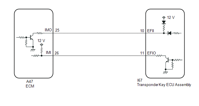
WIRING DIAGRAM
CAUTION / NOTICE / HINT
NOTICE:
If the transponder key ECU assembly or ECM is replaced, refer to Registration.
Click here .gif)
PROCEDURE
| 1. |
CLEAR DTC |
(a) Clear the DTCs.
Body Electrical > Immobiliser > Clear DTCs Powertrain > Engine > Clear DTCs
|
.gif)
| 2. |
CHECK FOR DTC |
(a) Check for DTCs.
Body Electrical > Immobiliser > Trouble Codes Powertrain > Engine > Trouble Codes| Result |
Proceed to |
|---|---|
| DTCs are not output |
A |
| DTCs are output |
B |
| B |
.gif) | GO TO DIAGNOSTIC TROUBLE CODE CHART |
|
| 3. |
READ VALUE USING GTS (IMMOBILISER FUEL CUT STATUS / IMMOBILISER FUEL CUT) |
(a) Read the Data List according to the display on the GTS.
Powertrain > Engine > Data List|
Tester Display | Measurement Item |
Range | Normal Condition |
Diagnostic Note |
|---|---|---|---|---|
|
Immobiliser Fuel Cut Status |
Status of immobiliser system fuel cut |
ON or OFF | OFF |
- |
|
Tester Display |
|---|
| Immobiliser Fuel Cut Status |
OK:
OFF is displayed after the engine is started.
| OK | | GO TO SFI SYSTEM |
|
| 4. |
CHECK WHETHER ENGINE STARTS |
(a) Using a registered door control transmitter assembly, turn the ignition switch to ON.
(b) Check that the engine starts 5 seconds after the ignition switch was turned to ON.
OK:
Engine starts normally.
| OK | | USE SIMULATION METHOD TO CHECK |
|
| 5. |
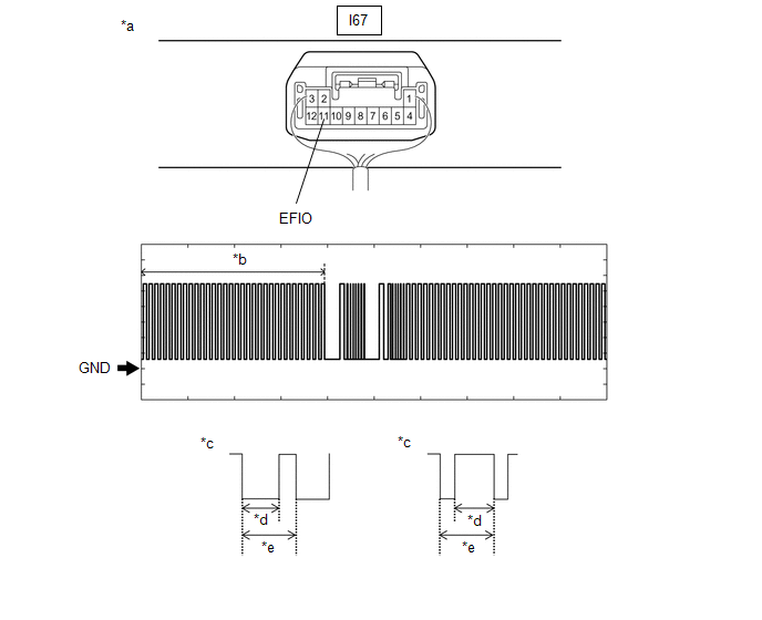
INSPECT TRANSPONDER KEY ECU ASSEMBLY (TERMINAL EFIO) |
(a) Using an oscilloscope, check the waveform.
|
*a | Component with harness connected (Transponder Key ECU Assembly) |
*b | Waveform |
|
*c | Waveform (detail) |
*d | Approximately 40 ms. |
|
*e | Approximately 60 ms. |
- | - |
|
Tester Connection | Condition |
Tool Setting | Specified Condition |
|---|---|---|---|
|
I67-11 (EFIO) - Body ground |
Within 3 seconds of starter operation and initial combustion, or within 3 seconds of ignition switch first being turned to ON after cable disconnected and reconnected to negative (-) auxiliary battery terminal |
2 V/DIV., 500 ms./DIV. |
Pulse generation (See waveform) |
|
Result | Proceed to |
|---|---|
|
Normal waveform | A |
|
Waveform not output, or has abnormal wavelength or shape |
B |
| B |
| GO TO STEP 10 |
|
| 6. |
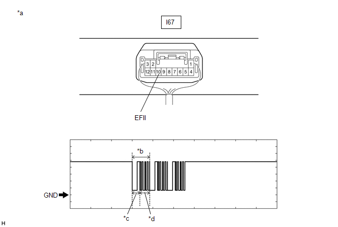
INSPECT TRANSPONDER KEY ECU ASSEMBLY (TERMINAL EFII) |
(a) Using an oscilloscope, check the waveform.
|
*a | Component with harness connected (Transponder Key ECU Assembly) |
*b | Waveform |
|
*c | Approximately 160 ms. |
*d | Approximately 270 ms. |
|
Tester Connection | Condition |
Tool Setting | Specified Condition |
|---|---|---|---|
|
I67-10 (EFII) - Body ground |
Within 3 seconds of starter operation and initial combustion, or within 3 seconds of ignition switch first being turned to ON after cable disconnected and reconnected to negative (-) auxiliary battery terminal |
2 V/DIV., 500 ms./DIV. |
Pulse generation (See waveform) |
|
Result | Proceed to |
|---|---|
|
Normal waveform | A |
|
Waveform not output, or has abnormal wavelength or shape |
B |
| B |
| REPLACE ECM
|
|
| 7. |
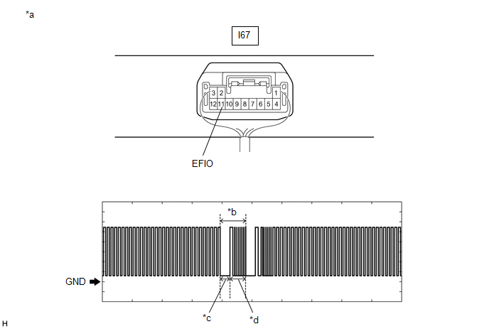
INSPECT TRANSPONDER KEY ECU ASSEMBLY (TERMINAL EFIO) |
(a) Using an oscilloscope, check the waveform.
|
*a | Component with harness connected (Transponder Key ECU Assembly) |
*b | Waveform |
|
*c | Approximately 160 ms. |
*d | Approximately 270 ms. |
|
Tester Connection | Condition |
Tool Setting | Specified Condition |
|---|---|---|---|
|
I67-11 (EFIO) - Body ground |
Within 3 seconds of starter operation and initial combustion, or within 3 seconds of ignition switch first being turned to ON after cable disconnected and reconnected to negative (-) auxiliary battery terminal |
2 V/DIV., 500 ms./DIV. |
Pulse generation (See waveform) |
|
Result | Proceed to |
|---|---|
|
Normal waveform | A |
|
Waveform not output, or has abnormal wavelength or shape |
B |
| B |
| REPLACE TRANSPONDER KEY ECU ASSEMBLY |
|
| 8. |
REGISTER ECU COMMUNICATION ID |
(a) Register the communication ID between the transponder key ECU assembly and ECM.
|
| 9. |
CHECK WHETHER ENGINE STARTS |
(a) Using a registered door control transmitter assembly, turn the ignition switch to ON.
(b) Check that the engine starts 5 seconds after the ignition switch was turned to ON.
OK:
Engine starts normally.
|
Result | Proceed to |
|---|---|
|
Engine can be started |
A |
| Engine cannot be started |
B |
| A |
| END (REGISTERED COMMUNICATION ID WAS DEFECTIVE) |
| B |
| REPLACE TRANSPONDER KEY ECU ASSEMBLY
|
| 10. |
CHECK HARNESS AND CONNECTOR (TRANSPONDER KEY ECU ASSEMBLY - ECM) |
(a) Disconnect the I67 transponder key ECU assembly connector.
(b) Disconnect the A47 ECM connector.
(c) Measure the resistance according to the value(s) in the table below.
Standard Resistance:
|
Tester Connection | Condition |
Specified Condition |
|---|---|---|
|
I67-11 (EFIO) - A47-26 (IMI) |
Always | Below 1 Ω |
|
I67-11 (EFIO) or A47-26 (IMI) - Other terminals and body ground |
Always | 10 kΩ or higher |
| OK | | REPLACE TRANSPONDER KEY ECU ASSEMBLY
|
| NG | | REPAIR OR REPLACE HARNESS OR CONNECTOR |


