Toyota Corolla Cross: P/W Master SW System Missing Message (B120687,B127387,B232187-B232487)
DESCRIPTION
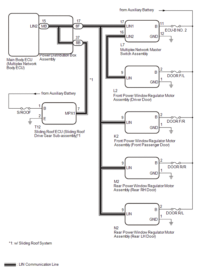
This DTC is stored when LIN communication between the main body ECU (multiplex network body ECU) and multiplex network master switch assembly, front power window regulator motor assembly (driver door), front power window regulator motor assembly (front passenger door), rear power window regulator motor assembly (rear RH door), rear power window regulator motor assembly (rear LH door) or sliding roof ECU (sliding roof drive gear sub-assembly)*1 stops for 10 seconds or more.
- *1: w/ Sliding Roof System
|
DTC No. |
Detection Item |
DTC Detection Condition |
Trouble Area |
|---|---|---|---|
|
B120687 |
P/W Master SW System Missing Message |
No communication between multiplex network master switch assembly and main body ECU (multiplex network body ECU) for 10 seconds or more. |
|
|
B127387 |
Sliding Roof System Missing Message |
No communication between sliding roof ECU (sliding roof drive gear sub-assembly) and main body ECU (multiplex network body ECU) for 10 seconds or more.*1 |
|
|
B232187 |
D-Door P/W System Missing Message |
No communication between front power window regulator motor assembly (driver door) and main body ECU (multiplex network body ECU) for 10 seconds or more. |
|
|
B232287 |
P-Door P/W System Missing Message |
No communication between front power window regulator motor assembly (front passenger door) and main body ECU (multiplex network body ECU) for 10 seconds or more. |
|
|
B232387 |
RR-Door P/W System Missing Message |
No communication between rear power window regulator motor assembly (rear RH door) and main body ECU (multiplex network body ECU) for 10 seconds or more. |
|
|
B232487 |
RL-Door P/W System Missing Message |
No communication between rear power window regulator motor assembly (rear LH door) and main body ECU (multiplex network body ECU) for 10 seconds or more. |
|
- *1: w/ Sliding Roof System
WIRING DIAGRAM
CAUTION / NOTICE / HINT
NOTICE:
- Inspect the fuses for circuits related to this system before performing the following procedure.
- When a power window regulator motor assembly is replaced or removed and
reinstalled, it is necessary to perform initialization.
Click here
.gif)
- When the sliding roof ECU (sliding roof drive gear sub-assembly) is replaced
or removed and reinstalled, it is necessary to perform initialization.*1
Click here
- *1: w/ Sliding Roof System
- Before replacing the main body ECU (multiplex network body ECU), refer to
Registration.
- for HEV Model: Click here
- for Gasoline Model: Click here
- for HEV Model: Click here
PROCEDURE
|
1. |
CLEAR DTC |
(a) Clear the DTCs.
Body Electrical > Main Body > Clear DTCs
|
.gif)
|
2. |
CHECK FOR DTC |
(a) Check for DTCs.
Body Electrical > Main Body > Trouble Codes|
Result |
Proceed to |
|---|---|
|
B120687, B127387, B232187, B232287, B232387 and B232487 are not output |
A |
|
B120687, B127387, B232187, B232287, B232387 and B232487 are output |
B |
|
B120687, B232187, B232287, B232387 and B232487 are output |
C |
|
B120687 and B232187 are output |
D |
|
Only B120687 is output |
E |
|
Only B127387 is output |
F |
|
Only B232187 is output |
G |
|
Only B232287 is output |
H |
|
Only B232387 is output |
I |
|
Only B232487 is output |
J |
| A | .gif) |
USE SIMULATION METHOD TO CHECK |
| C | |
GO TO STEP 4 |
| D | |
GO TO STEP 6 |
| E | |
GO TO STEP 7 |
| F | |
GO TO STEP 8 |
| G | |
GO TO STEP 11 |
| H | |
GO TO STEP 14 |
| I | |
GO TO STEP 16 |
| J | |
GO TO STEP 18 |
|
|
3. |
INSPECT POWER DISTRIBUTION BOX ASSEMBLY |
(a) Remove the power distribution box assembly.
HINT:
Click here
(b) Remove the main body ECU (multiplex network body ECU) from the power distribution box assembly.
(c) Measure the resistance according to the value(s) in the table below.
|
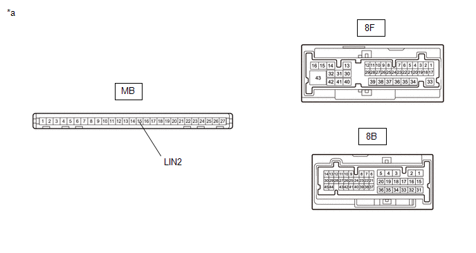
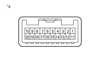
*a |
Component without harness connected (Power Distribution Box Assembly) |
- |
- |
HINT:
This inspection is to check the LIN communication line in the power distribution box assembly that connects the wire harness to the built-in main body ECU (multiplex network body ECU).
Standard Resistance:
|
Tester Connection |
Condition |
Specified Condition |
|---|---|---|
|
MB-15 (LIN2) - 8F-17 |
Always |
Below 1 Ω |
|
MB-15 (LIN2) - 8B-37 |
Always |
Below 1 Ω |
| OK | |
REPLACE MAIN BODY ECU (MULTIPLEX NETWORK BODY ECU) |
| NG | |
REPLACE POWER DISTRIBUTION BOX ASSEMBLY |
|
4. |
INSPECT POWER DISTRIBUTION BOX ASSEMBLY |
(a) Remove the power distribution box assembly.
HINT:
Click here
(b) Remove the main body ECU (multiplex network body ECU) from the power distribution box assembly.
(c) Measure the resistance according to the value(s) in the table below.
|
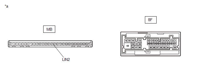
*a |
Component without harness connected (Power Distribution Box Assembly) |
- |
- |
HINT:
This inspection is to check the LIN communication line in the power distribution box assembly that connects the wire harness to the built-in main body ECU (multiplex network body ECU).
Standard Resistance:
|
Tester Connection |
Condition |
Specified Condition |
|---|---|---|
|
MB-15 (LIN2) - 8F-17 |
Always |
Below 1 Ω |
| NG | |
REPLACE POWER DISTRIBUTION BOX ASSEMBLY |
|
|
5. |
CHECK HARNESS AND CONNECTOR (POWER DISTRIBUTION BOX ASSEMBLY - MULTIPLEX NETWORK MASTER SWITCH ASSEMBLY) |
(a) Disconnect the L7 multiplex network master switch assembly connector.
(b) Measure the resistance according to the value(s) in the table below.
NOTICE:
Make sure that each ECU is in sleep mode before performing the inspection. To enter sleep mode, turn the ignition switch from ON to off and wait for 180 seconds or more without operating any switches.
Standard Resistance:
|
Tester Connection |
Switch Condition |
Specified Condition |
|---|---|---|
|
8F-17 - L7-17 (LIN1) |
Ignition switch off |
Below 1 Ω |
| OK | |
REPLACE MAIN BODY ECU (MULTIPLEX NETWORK BODY ECU) |
| NG | |
REPAIR OR REPLACE HARNESS OR CONNECTOR |
|
6. |
CHECK HARNESS AND CONNECTOR (POWER DISTRIBUTION BOX ASSEMBLY - MULTIPLEX NETWORK MASTER SWITCH ASSEMBLY) |
(a) Disconnect the 8F power distribution box assembly connector.
(b) Disconnect the L7 multiplex network master switch assembly connector.
(c) Measure the resistance according to the value(s) in the table below.
NOTICE:
Make sure that each ECU is in sleep mode before performing the inspection. To enter sleep mode, turn the ignition switch from ON to off and wait for 180 seconds or more without operating any switches.
Standard Resistance:
|
Tester Connection |
Switch Condition |
Specified Condition |
|---|---|---|
|
8F-17 - L7-17 (LIN1) |
Ignition switch off |
Below 1 Ω |
| OK | |
REPLACE MULTIPLEX NETWORK MASTER SWITCH ASSEMBLY |
| NG | |
REPAIR OR REPLACE HARNESS OR CONNECTOR |
|
7. |
CHECK HARNESS AND CONNECTOR (MULTIPLEX NETWORK MASTER SWITCH ASSEMBLY - AUXILIARY BATTERY AND BODY GROUND) |
(a) Disconnect the L7 multiplex network master switch assembly connector.
(b) Measure the voltage according to the value(s) in the table below.
Standard Voltage:
|
Tester Connection |
Switch Condition |
Specified Condition |
|---|---|---|
|
L7-11 (B) - L7-12 (GND) |
Ignition switch off |
11 to 14 V |
(c) Measure the resistance according to the value(s) in the table below.
Standard Resistance:
|
Tester Connection |
Condition |
Specified Condition |
|---|---|---|
|
L7-12 (GND) - Body ground |
Always |
Below 1 Ω |
| OK | |
REPLACE MULTIPLEX NETWORK MASTER SWITCH ASSEMBLY |
| NG | |
REPAIR OR REPLACE HARNESS OR CONNECTOR |
|
8. |
INSPECT POWER DISTRIBUTION BOX ASSEMBLY |
(a) Remove the power distribution box assembly.
HINT:
Click here
(b) Remove the main body ECU (multiplex network body ECU) from the power distribution box assembly.
(c) Measure the resistance according to the value(s) in the table below.
|
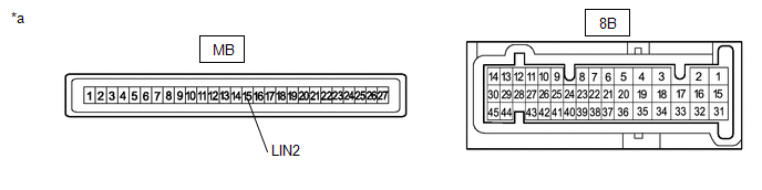
*a |
Component without harness connected (Power Distribution Box Assembly) |
- |
- |
HINT:
This inspection is to check the LIN communication line in the power distribution box assembly that connects the wire harness to the built-in main body ECU (multiplex network body ECU).
Standard Resistance:
|
Tester Connection |
Condition |
Specified Condition |
|---|---|---|
|
MB-15 (LIN2) - 8B-37 |
Always |
Below 1 Ω |
| NG | |
REPLACE POWER DISTRIBUTION BOX ASSEMBLY |
|
|
9. |
CHECK HARNESS AND CONNECTOR (POWER DISTRIBUTION BOX ASSEMBLY - SLIDING ROOF ECU (SLIDING ROOF DRIVE GEAR SUB-ASSEMBLY)) |
(a) Disconnect the T12 sliding roof ECU (sliding roof drive gear sub-assembly) connector.
(b) Measure the resistance according to the value(s) in the table below.
NOTICE:
Make sure that each ECU is in sleep mode before performing the inspection. To enter sleep mode, turn the ignition switch from ON to off and wait for 180 seconds or more without operating any switches.
Standard Resistance:
|
Tester Connection |
Switch Condition |
Specified Condition |
|---|---|---|
|
8B-37 - T12-7 (MPX1) |
Ignition switch off |
Below 1 Ω |
| NG | |
REPAIR OR REPLACE HARNESS OR CONNECTOR |
|
|
10. |
CHECK HARNESS AND CONNECTOR (SLIDING ROOF ECU (SLIDING ROOF DRIVE GEAR SUB-ASSEMBLY) - AUXILIARY BATTERY AND BODY GROUND) |
(a) Measure the voltage according to the value(s) in the table below.
Standard Voltage:
|
Tester Connection |
Switch Condition |
Specified Condition |
|---|---|---|
|
T12-1 (B) - T12-2 (E) |
Ignition switch off |
11 to 14 V |
(b) Measure the resistance according to the value(s) in the table below.
Standard Resistance:
|
Tester Connection |
Condition |
Specified Condition |
|---|---|---|
|
T12-2 (E) - Body ground |
Always |
Below 1 Ω |
| OK | |
REPLACE SLIDING ROOF ECU (SLIDING ROOF DRIVE GEAR SUB-ASSEMBLY) |
| NG | |
REPAIR OR REPLACE HARNESS OR CONNECTOR |
|
11. |
INSPECT MULTIPLEX NETWORK MASTER SWITCH ASSEMBLY |
(a) Remove the multiplex network master switch assembly.
HINT:
Click here
|
(b) Measure the resistance according to the value(s) in the table below. Standard Resistance:
|
|
| NG | |
REPLACE MULTIPLEX NETWORK MASTER SWITCH ASSEMBLY |
|
|
12. |
CHECK HARNESS AND CONNECTOR (MULTIPLEX NETWORK MASTER SWITCH ASSEMBLY - FRONT POWER WINDOW REGULATOR MOTOR ASSEMBLY (DRIVER DOOR)) |
(a) Disconnect the L2 front power window regulator motor assembly (driver door) connector.
(b) Measure the resistance according to the value(s) in the table below.
Standard Resistance:
|
Tester Connection |
Condition |
Specified Condition |
|---|---|---|
|
L7-16 (LIN2) - L2-9 (LIN) |
Always |
Below 1 Ω |
| NG | |
REPAIR OR REPLACE HARNESS OR CONNECTOR |
|
|
13. |
CHECK HARNESS AND CONNECTOR (FRONT POWER WINDOW REGULATOR MOTOR ASSEMBLY (DRIVER DOOR) - AUXILIARY BATTERY AND BODY GROUND) |
(a) Measure the voltage according to the value(s) in the table below.
Standard Voltage:
|
Tester Connection |
Switch Condition |
Specified Condition |
|---|---|---|
|
L2-2 (B) - L2-1 (GND) |
Ignition switch off |
11 to 14 V |
(b) Measure the resistance according to the value(s) in the table below.
Standard Resistance:
|
Tester Connection |
Condition |
Specified Condition |
|---|---|---|
|
L2-1 (GND) - Body ground |
Always |
Below 1 Ω |
| OK | |
REPLACE FRONT POWER WINDOW REGULATOR MOTOR ASSEMBLY (DRIVER DOOR) |
| NG | |
REPAIR OR REPLACE HARNESS OR CONNECTOR |
|
14. |
CHECK HARNESS AND CONNECTOR (POWER DISTRIBUTION BOX ASSEMBLY - FRONT POWER WINDOW REGULATOR MOTOR ASSEMBLY (FRONT PASSENGER DOOR)) |
(a) Disconnect the 8F power distribution box assembly connector.
(b) Disconnect the K2 front power window regulator motor assembly (front passenger door) connector.
(c) Measure the resistance according to the value(s) in the table below.
NOTICE:
Make sure that each ECU is in sleep mode before performing the inspection. To enter sleep mode, turn the ignition switch from ON to off and wait for 180 seconds or more without operating any switches.
Standard Resistance:
|
Tester Connection |
Switch Condition |
Specified Condition |
|---|---|---|
|
8F-17 - K2-9 (LIN) |
Ignition switch off |
Below 1 Ω |
| NG | |
REPAIR OR REPLACE HARNESS OR CONNECTOR |
|
|
15. |
CHECK HARNESS AND CONNECTOR (FRONT POWER WINDOW REGULATOR MOTOR ASSEMBLY (FRONT PASSENGER DOOR) - AUXILIARY BATTERY AND BODY GROUND) |
(a) Measure the voltage according to the value(s) in the table below.
Standard Voltage:
|
Tester Connection |
Switch Condition |
Specified Condition |
|---|---|---|
|
K2-2 (B) - K2-1 (GND) |
Ignition switch off |
11 to 14 V |
(b) Measure the resistance according to the value(s) in the table below.
Standard Resistance:
|
Tester Connection |
Condition |
Specified Condition |
|---|---|---|
|
K2-1 (GND) - Body ground |
Always |
Below 1 Ω |
| OK | |
REPLACE FRONT POWER WINDOW REGULATOR MOTOR ASSEMBLY (FRONT PASSENGER DOOR) |
| NG | |
REPAIR OR REPLACE HARNESS OR CONNECTOR |
|
16. |
CHECK HARNESS AND CONNECTOR (POWER DISTRIBUTION BOX ASSEMBLY - REAR POWER WINDOW REGULATOR MOTOR ASSEMBLY (REAR RH DOOR)) |
(a) Disconnect the 8F power distribution box assembly connector.
(b) Disconnect the M2 rear power window regulator motor assembly (rear RH door) connector.
(c) Measure the resistance according to the value(s) in the table below.
NOTICE:
Make sure that each ECU is in sleep mode before performing the inspection. To enter sleep mode, turn the ignition switch from ON to off and wait for 180 seconds or more without operating any switches.
Standard Resistance:
|
Tester Connection |
Switch Condition |
Specified Condition |
|---|---|---|
|
8F-17 - M2-9 (LIN) |
Ignition switch off |
Below 1 Ω |
| NG | |
REPAIR OR REPLACE HARNESS OR CONNECTOR |
|
|
17. |
CHECK HARNESS AND CONNECTOR (REAR POWER WINDOW REGULATOR MOTOR ASSEMBLY (REAR RH DOOR) - AUXILIARY BATTERY AND BODY GROUND) |
(a) Measure the voltage according to the value(s) in the table below.
Standard Voltage:
|
Tester Connection |
Switch Condition |
Specified Condition |
|---|---|---|
|
M2-2 (B) - M2-1 (GND) |
Ignition switch off |
11 to 14 V |
(b) Measure the resistance according to the value(s) in the table below.
Standard Resistance:
|
Tester Connection |
Condition |
Specified Condition |
|---|---|---|
|
M2-1 (GND) - Body ground |
Always |
Below 1 Ω |
| OK | |
REPLACE REAR POWER WINDOW REGULATOR MOTOR ASSEMBLY (REAR RH DOOR) |
| NG | |
REPAIR OR REPLACE HARNESS OR CONNECTOR |
|
18. |
CHECK HARNESS AND CONNECTOR (POWER DISTRIBUTION BOX ASSEMBLY - REAR POWER WINDOW REGULATOR MOTOR ASSEMBLY (REAR LH DOOR)) |
(a) Disconnect the 8F power distribution box assembly connector.
(b) Disconnect the N2 rear power window regulator motor assembly (rear LH door) connector.
(c) Measure the resistance according to the value(s) in the table below.
NOTICE:
Make sure that each ECU is in sleep mode before performing the inspection. To enter sleep mode, turn the ignition switch from ON to off and wait for 180 seconds or more without operating any switches.
Standard Resistance:
|
Tester Connection |
Switch Condition |
Specified Condition |
|---|---|---|
|
8F-17 - N2-9 (LIN) |
Ignition switch off |
Below 1 Ω |
| NG | |
REPAIR OR REPLACE HARNESS OR CONNECTOR |
|
|
19. |
CHECK HARNESS AND CONNECTOR (REAR POWER WINDOW REGULATOR MOTOR ASSEMBLY (REAR LH DOOR) - AUXILIARY BATTERY AND BODY GROUND) |
(a) Measure the voltage according to the value(s) in the table below.
Standard Voltage:
|
Tester Connection |
Switch Condition |
Specified Condition |
|---|---|---|
|
N2-2 (B) - N2-1 (GND) |
Ignition switch off |
11 to 14 V |
(b) Measure the resistance according to the value(s) in the table below.
Standard Resistance:
|
Tester Connection |
Condition |
Specified Condition |
|---|---|---|
|
N2-1 (GND) - Body ground |
Always |
Below 1 Ω |
| OK | |
REPLACE REAR POWER WINDOW REGULATOR MOTOR ASSEMBLY (REAR LH DOOR) |
| NG | |
REPAIR OR REPLACE HARNESS OR CONNECTOR |


