Toyota Corolla Cross: Key Cannot be Registered
DESCRIPTION
A maximum of 5 key ID codes can be registered.
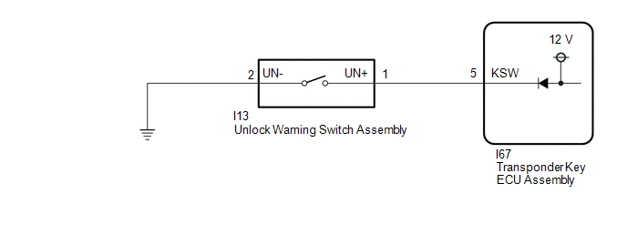
WIRING DIAGRAM
CAUTION / NOTICE / HINT
NOTICE:
If the transponder key ECU assembly is replaced, refer to Registration.
Click here .gif)
PROCEDURE
| 1. |
CHECK REGISTRATION MODE |
(a) Check that the system enters registration mode.
OK:
System enters registration mode.
| NG | .gif) | GO TO STEP 5 |
|
.gif)
| 2. |
CHECK SECURITY INDICATOR LIGHT (COMBINATION METER ASSEMBLY) OPERATION |
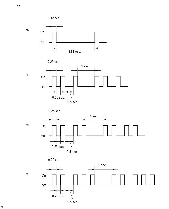
(a) In registration mode, insert the door control transmitter assembly into the ignition key cylinder and check the security indicator light (combination meter assembly).
HINT:
If the new key ID code registration fails, code 2-1 will be output through the security light. Trying to re-register an already registered door control transmitter assembly will cause code 2-2 to be output when the door control transmitter assembly is inserted. If the number of registered key ID codes exceeds the maximum limit, code 2-3 will be output through the security indicator light (combination meter assembly). The output details are shown in the following illustration.
|
*a | Security Indicator Light (Combination Meter Assembly) |
*b | Normal (Immobiliser system is operating normally) |
|
*c | Code 2-1 |
*d | Code 2-2 |
|
*e | Code 2-3 |
- | - |
|
Result | Proceed to |
|---|---|
|
Code 2-1 or Code 2-3 is output |
A |
| Code 2-2 is output |
B |
| B |
| END (REGISTERED DOOR CONTROL TRANSMITTER ASSEMBLY WAS USED) |
|
| 3. |
READ VALUE USING GTS (TRANSPONDER M-CODE) |
(a) Read the Data List according to the display on the GTS.
Body Electrical > Immobiliser > Data List|
Tester Display | Measurement Item |
Range | Normal Condition |
Diagnostic Note |
|---|---|---|---|---|
|
Transponder M-code | Number of registered master key |
min. 0, max. 15 | Number of registered master keys displayed |
- |
|
Tester Display |
|---|
| Transponder M-code |
|
Result | Proceed to |
|---|---|
|
5 is displayed for "Transponder M-code" |
A |
| Values are other than above |
B |
| A |
| MAXIMUM NUMBER OF DOOR CONTROL TRANSMITTER ASSEMBLIES ALREADY REGISTERED |
|
| 4. |
KEY REGISTRATION |
(a) Refer to the table below to determine if additional door control transmitter assemblies can be registered.
|
Number of Door Control Transmitter Assemblies Registered |
Proceed to |
|---|---|
| 0 |
New key ID code registration |
|
1 to 5 | Additional key ID code registration |
(b) Check if an additional door control transmitter assembly can be registered.
OK:
Additional door control transmitter assembly can be registered.
| OK | | END (DOOR CONTROL TRANSMITTER ASSEMBLY MALFUNCTION) |
| NG | | REPLACE TRANSPONDER KEY ECU ASSEMBLY
|
| 5. |
INSPECT UNLOCK WARNING SWITCH ASSEMBLY |
Click here
| NG | | REPLACE UNLOCK WARNING SWITCH ASSEMBLY |
|
| 6. |
CHECK HARNESS AND CONNECTOR (TRANSPONDER KEY ECU ASSEMBLY - UNLOCK WARNING SWITCH ASSEMBLY) |
(a) Disconnect the I67 transponder key ECU assembly connector.
(b) Measure the resistance according to the value(s) in the table below.
Standard Resistance:
|
Tester Connection | Condition |
Specified Condition |
|---|---|---|
|
I13-1 (UN+) - I67-5 (KSW) |
Always | Below 1 Ω |
|
I13-2 (UN-) - Body ground |
Always | Below 1 Ω |
|
I13-1 (UN+) or I67-5 (KSW) - Other terminals and body ground |
Always | 10 kΩ or higher |
| OK | | REPLACE TRANSPONDER KEY ECU ASSEMBLY
|
| NG | | REPAIR OR REPLACE HARNESS OR CONNECTOR |
READ NEXT:
 Security Horn Assembly
RemovalREMOVAL CAUTION / NOTICE / HINT COMPONENTS (REMOVAL)
Procedure Part Name Code
1 SECURITY HORN ASSEMBLY
86510A -
- - PROCEDURE
1. REMO
Precaution
PRECAUTION PRECAUTION FOR DISCONNECTING CABLE FROM NEGATIVE (-) AUXILIARY BATTERY TERMINAL
NOTICE: After the ignition switch is turned off, there may be a waiting time before disconnecting the negat
SEE MORE:
 Lost Communication with ECM/PCM "A" (ch5) Missing Message (U115C87)
DESCRIPTION The ECM and skid control ECU (brake actuator assembly) send and receive signals via CAN communication.
If a communication error occurs between the ECM and skid control ECU (brake actuator assembly), the ECM stores this DTC.
DTC No. Detection Item
DTC Detection Condition
Calibration
CALIBRATION
POWER STEERING ECU INITIAL SETTING (ASSIST MAP WRITING) (USING GTS)
NOTICE:
If any of the following conditions are met, perform Power Steering ECU Initial
Setting (assist map writing):
The power steering ECU assembly has been replaced.
The electric power steering column sub-a
