Toyota Corolla Cross: Engine does not Start
DESCRIPTION
When the electrical key transmitter sub-assembly is in the cabin and the engine switch is pressed, the certification ECU (smart key ECU assembly) receives a signal and changes the power source mode. Additionally, when the shift lever is in P and the brake pedal is depressed, the engine can be started by pressing the engine switch.
Related Data List and Active Test Items|
Problem Symptom | Data List and Active Test |
|---|---|
|
Engine does not start | Power Source Control
|
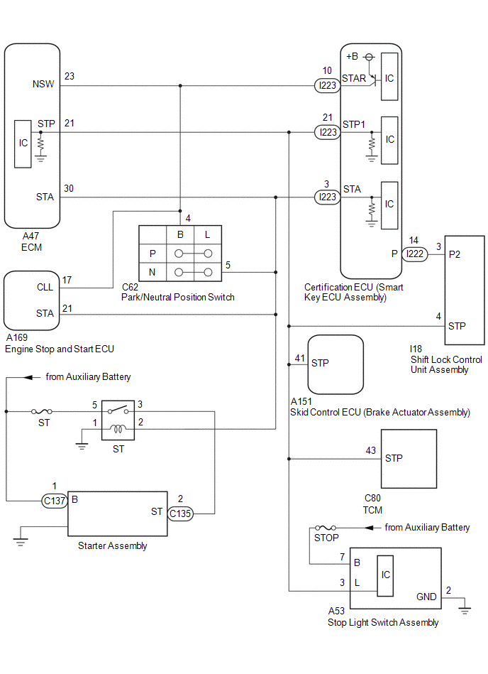
WIRING DIAGRAM
CAUTION / NOTICE / HINT
NOTICE:
- When using the GTS with the engine switch off, connect the GTS to the DLC3 and turn a courtesy light switch on and off at intervals of 1.5 seconds or less until communication between the GTS and the vehicle begins. Then select the vehicle type under manual mode and enter the following menus: Body Electrical / Smart Key System. While using the GTS, periodically turn a courtesy light switch on and off at intervals of 1.5 seconds or less to maintain communication between the GTS and the vehicle.
- If the smart key system (for Start Function) has been disabled, enable the system before performing troubleshooting.
Click here
.gif)
- Inspect the fuses for circuits related to this system before performing the following procedure.
- Before replacing the certification ECU (smart key ECU assembly) or an electrical key transmitter sub-assembly, refer to Registration.
Click here
- After completing repairs, confirm that the problem does not recur.
- After performing repairs, confirm that no DTCs are output by performing "DTC Output Confirmation Operation."
PROCEDURE
|
1. | CHECK WHETHER ENGINE STARTS |
(a) Using an electrical key transmitter sub-assembly which is registered to the vehicle, turn the ignition switch to ON.
(b) Check that the engine can be started 5 seconds after the ignition switch turned to ON.
OK:
Engine starts normally.
| OK | .gif) | CHECK VEHICLE CONTROL HISTORY (ROB) |
|
.gif)
| 2. |
CHECK SECURITY INDICATOR LIGHT (IMMOBILISER FUNCTION UNSET) |
(a) Get into the vehicle while carrying an electrical key transmitter sub-assembly.
(b) Move the shift lever to P.
(c) Press the engine switch with the brake pedal released and check that the security indicator light changes from blinking to off at the same time that the power source mode changes to ACC.
OK:
The security indicator light changes from blinking to off at the same time that the power source mode changes to ACC.
HINT:
The immobiliser function can be determined to be operating correctly if the security indicator light changes from blinking to off at the same time that the power source mode changes to ACC.
| NG | | GO TO OTHER PROBLEM (Immobiliser System does not Operate Properly) |
|
| 3. |
CHECK FOR DTC |
(a) Using the GTS, check if LIN communication DTC B278588 and B278987 are output.
Body Electrical > Smart Key > Trouble CodesOK:
DTC B278588 and B278987 are not output.
| NG | | GO TO LIN COMMUNICATION SYSTEM (DTC B278588) |
|
| 4. |
CHECK ENGINE CRANKING OPERATION |
(a) Get into the vehicle while carrying an electrical key transmitter sub-assembly.
(b) Move the shift lever to P.
(c) Check that the key indicator display is displayed on the multi-information display in the combination meter assembly, and then press the engine switch and check that the engine cranks.
|
Result | Proceed to |
|---|---|
|
Engine cranks and initial combustion occurs |
A |
| Engine cranks but initial combustion does not occur |
B |
| Engine does not crank |
C |
| A |
| GO TO OTHER PROBLEM (Immobiliser System does not Operate Properly) |
| B |
| GO TO SFI SYSTEM |
|
| 5. |
CHECK ENGINE SWITCH CONDITION |
(a) Get into the vehicle while carrying an electrical key transmitter sub-assembly.
(b) Move the shift lever to P.
(c) With the brake pedal released, check that pressing the engine switch causes the power source mode to change.
|
Result | Proceed to |
|---|---|
|
Power source mode changes : Off → ACC → ON → off |
A |
| Power source mode does not change to ACC or ON |
B |
| Power source mode changes to ON but not to ACC |
C |
| Power source mode changes to ACC but not to ON |
D |
| B |
| GO TO OTHER PROBLEM (Power Source Mode does not Change to ON (IG and ACC)) |
| C |
| GO TO OTHER PROBLEM (Power Source Mode does not Change to ON (ACC)) |
| D |
| GO TO OTHER PROBLEM (Power Source Mode does not Change to ON (IG)) |
|
| 6. |
READ VALUE USING GTS (STOP LIGHT SWITCH) |
(a) Read the Data List according to the display on the GTS.
Body Electrical > Power Source Control > Data List|
Tester Display | Measurement Item |
Range | Normal Condition |
Diagnostic Note |
|---|---|---|---|---|
|
Stop Light Switch | State of brake pedal |
OFF or ON | OFF: Brake pedal released ON: Brake pedal depressed |
|
|
Tester Display |
|---|
| Stop Light Switch |
OK:
The GTS display changes correctly in response to the brake pedal operation.
| NG | | GO TO STEP 26 |
|
| 7. |
READ VALUE USING GTS (SHIFT P SIGNAL) |
(a) Move the shift lever to P.
(b) Read the Data List according to the display on the GTS.
Body Electrical > Power Source Control > Data List|
Tester Display | Measurement Item |
Range | Normal Condition |
Diagnostic Note |
|---|---|---|---|---|
|
Shift P Signal | Shift position P |
OFF or ON | OFF: Shift lever not in P ON: Shift lever in P |
|
|
Tester Display |
|---|
| Shift P Signal |
OK:
ON is displayed on the GTS.
| NG | | GO TO STEP 23 |
|
| 8. |
READ VALUE USING GTS (SHIFT P/N (STARTING CONTROL)) |
(a) Read the Data List according to the display on the GTS.
Body Electrical > Power Source Control > Data List|
Tester Display | Measurement Item |
Range | Normal Condition |
Diagnostic Note |
|---|---|---|---|---|
|
Shift P/N (Starting Control) |
Park/Neutral position switch status |
OFF or ON | OFF: Shift lever not in P or N ON: Shift lever in P or N |
When OFF is displayed, the engine will not crank. |
|
Tester Display |
|---|
| Shift P/N (Starting Control) |
OK:
The GTS display changes correctly in response to the shift lever or brake pedal operation.
| NG | | GO TO STEP 17 |
|
| 9. |
READ VALUE USING GTS (POWER SUPPLY CONDITION) |
(a) Read the Data List according to the display on the GTS.
Body Electrical > Power Source Control > Data List|
Tester Display | Measurement Item |
Range | Normal Condition |
Diagnostic Note |
|---|---|---|---|---|
|
Power Supply Condition |
Power supply state | OFF, ACC ON, IGR ON, IGP ON or Starter ON |
OFF: Ignition switch off ACC ON: Ignition switch ACC IGR ON: Ignition switch ON IGP ON: Ignition switch ON Starter ON: Sending engine start request signal |
- |
|
Tester Display |
|---|
| Power Supply Condition |
NOTICE:
Check that the key indicator display is displayed on the multi-information display in the combination meter assembly, and then press the engine switch.
OK:
The GTS display changes correctly in response to the engine switch operation.
| NG | | REPLACE CERTIFICATION ECU (SMART KEY ECU ASSEMBLY) |
|
| 10. |
READ VALUE USING GTS (STARTER RELAY DRIVING REQUEST (STARTING CONTROL)) |
(a) Get into the vehicle while carrying an electrical key transmitter sub-assembly.
(b) Move the shift lever to P.
(c) According to the display on the GTS, read the Data List while pressing the engine switch with the brake pedal depressed.
Body Electrical > Power Source Control > Data List|
Tester Display | Measurement Item |
Range | Normal Condition |
Diagnostic Note |
|---|---|---|---|---|
|
Starter Relay Driving Request (Starting Control) |
Engine start request signal status |
OFF or ON | OFF: The engine switch is not pressed ON: With the shift lever in P and the brake pedal depressed, the engine switch is pressed and held |
|
|
Tester Display |
|---|
| Starter Relay Driving Request (Starting Control) |
OK:
The GTS display changes.
| NG | | REPLACE CERTIFICATION ECU (SMART KEY ECU ASSEMBLY) |
|
| 11. |
CHECK HARNESS AND CONNECTOR (CERTIFICATION ECU (SMART KEY ECU ASSEMBLY) - ST RELAY) |
| (a) Measure the voltage according to the value(s) in the table below. Standard Voltage:
HINT: *: While the engine is cranking, the auxiliary battery voltage may drop to approximately 6 V. |
|
| NG | | GO TO STEP 16 |
|
| 12. |
CHECK HARNESS AND CONNECTOR (ST RELAY - AUXILIARY BATTERY AND GROUND) |
| (a) Measure the resistance according to the value(s) in the table below. Standard Resistance:
|
|
(b) Measure the voltage according to the value(s) in the table below.
Standard Voltage:
|
Tester Connection | Condition |
Specified Condition |
|---|---|---|
|
No. 1 engine room relay block assembly ST relay terminal 5 - Body ground |
Always | 11 to 14 V |
| NG | | REPAIR OR REPLACE HARNESS OR CONNECTOR |
|
| 13. |
INSPECT ST RELAY |
Click here
| NG | |
REPLACE ST RELAY |
|
| 14. |
CHECK HARNESS AND CONNECTOR (STARTER ASSEMBLY - ST RELAY) |
(a) Disconnect the C132 starter assembly connector.
(b) Measure the resistance according to the value(s) in the table below.
Standard Resistance:
|
Tester Connection | Condition |
Specified Condition |
|---|---|---|
|
No. 1 engine room relay block assembly ST relay terminal 3 - C135-2 |
Always | Below 1 Ω |
|
No. 1 engine room relay block assembly ST relay terminal 3 or C135-2 - Other terminals and body ground |
Always | 10 kΩ or higher |
| NG | | REPAIR OR REPLACE HARNESS OR CONNECTOR |
|
| 15. |
CHECK HARNESS AND CONNECTOR (STARTER ASSEMBLY - AUXILIARY BATTERY) |
(a) Disconnect the C137 starter assembly connector.
(b) Measure the voltage according to the value(s) in the table below.
Standard Voltage:
|
Tester Connection | Condition |
Specified Condition |
|---|---|---|
|
C137-1 (B) - Body ground |
Always | 11 to 14 V |
| OK | | REPLACE STARTER ASSEMBLY |
| NG | | REPAIR OR REPLACE HARNESS OR CONNECTOR |
| 16. |
CHECK HARNESS AND CONNECTOR (PARK/NEUTRAL POSITION SWITCH - ST RELAY) |
(a) Disconnect the C62 park/neutral position switch connector.
(b) Disconnect the A169 engine stop and start ECU connector.
(c) Measure the resistance according to the value(s) in the table below.
Standard Resistance:
|
Tester Connection | Condition |
Specified Condition |
|---|---|---|
|
C62-5 (L) - 2 (ST relay) |
Always | Below 1 Ω |
|
C62-5 (L) or 2 (ST relay) - Other terminals and body ground |
Always | 10 kΩ or higher |
| OK | | REPAIR OR REPLACE HARNESS OR CONNECTOR |
| NG | | REPLACE CERTIFICATION ECU (SMART KEY ECU ASSEMBLY) |
| 17. |
READ VALUE USING GTS (NEUTRAL SW/ CLUTCH SW) |
(a) Disconnect the A47 ECM connector.
(b) Read the Data List according to the display on the GTS.
Body Electrical > Power Source Control > Data List|
Tester Display | Measurement Item |
Range | Normal Condition |
Diagnostic Note |
|---|---|---|---|---|
|
Neutral Switch / Clutch Switch |
Shift position (P and N) |
OFF or ON | OFF: Shift lever in any position other than P or N ON: Shift lever in P or N |
|
|
Tester Display |
|---|
| Neutral Switch / Clutch Switch |
OK:
The GTS display changes correctly in response to the shift lever or brake pedal operation.
| OK | | REPLACE ECM |
|
| 18. |
READ VALUE USING GTS (NEUTRAL SW/ CLUTCH SW) |
(a) Disconnect the A169 engine stop and start ECU connector.
(b) Read the Data List according to the display on the GTS.
Body Electrical > Power Source Control > Data List|
Tester Display | Measurement Item |
Range | Normal Condition |
Diagnostic Note |
|---|---|---|---|---|
|
Neutral Switch / Clutch Switch |
Shift position (P and N) |
OFF or ON | OFF: Shift lever in any position other than P or N ON: Shift lever in P or N |
|
|
Tester Display |
|---|
| Neutral Switch / Clutch Switch |
OK:
The GTS display changes correctly in response to the shift lever operation.
| OK | | REPLACE ENGINE STOP AND START ECU |
|
| 19. |
INSPECT PARK/NEUTRAL POSITION SWITCH |
for 2WD: Click here
for AWD: Click here
| NG | |
REPLACE PARK/NEUTRAL POSITION SWITCH for 2WD: Click here for AWD: Click here
|
|
| 20. |
CHECK HARNESS AND CONNECTOR (CERTIFICATION ECU (SMART KEY ECU ASSEMBLY) - PARK/NEUTRAL POSITION SWITCH) |
(a) Disconnect the I223 certification ECU (smart key ECU assembly) connector.
(b) Disconnect the C62 park/neutral position switch connector.
(c) Remove the ST relay.
(d) Measure the resistance according to the value(s) in the table below.
Standard Resistance:
|
Tester Connection | Condition |
Specified Condition |
|---|---|---|
|
I223-3 (STA) - C62-5 (L) |
Always | Below 1 Ω |
|
I223-3 (STA) - A169-21 (STA) |
Always | Below 1 Ω |
|
I223-10 (STAR) - A47-23 (NSW) |
Always | Below 1 Ω |
|
I223-10 (STAR) - C62-4 (B) |
Always | Below 1 Ω |
|
I223-10 (STAR) - A169-17 (CLL) |
Always | Below 1 Ω |
|
I223-3 (STA) or C62-5 (L) - Other terminals and body ground |
Always | 10 kΩ or higher |
|
I223-10 (STAR) or A47-23 (NSW) - Other terminals and body ground |
Always | 10 kΩ or higher |
|
I223-10 (STAR) or C62-4 (B) - Other terminals and body ground |
Always | 10 kΩ or higher |
| NG | | REPAIR OR REPLACE HARNESS OR CONNECTOR |
|
| 21. |
CHECK CERTIFICATION ECU (SMART KEY ECU ASSEMBLY) |
(a) Connect the I223 certification ECU (smart key ECU assembly) connector.
(b) Measure the voltage according to the value(s) in the table below.
Standard Voltage:
|
Tester Connection | Condition |
Specified Condition |
|---|---|---|
|
I223-10 (STAR) - Body ground |
Engine switch pressed and held with brake pedal depressed (starter on) → Approximately 1 second after engine switch released (starter off) |
6 V or higher* → 1.0 V or less |
HINT:
*: While the engine is cranking, the auxiliary battery voltage may drop to approximately 6 V.
| NG | | REPLACE CERTIFICATION ECU (SMART KEY ECU ASSEMBLY) |
|
| 22. |
INSPECT ST RELAY |
Click here
| OK | |
REPLACE CERTIFICATION ECU (SMART KEY ECU ASSEMBLY) |
| NG | | REPLACE ST RELAY |
| 23. |
CHECK SHIFT LOCK CONTROL UNIT ASSEMBLY |
(a) Measure the voltage according to the value(s) in the table below.
Standard Voltage:
|
Tester Connection | Condition |
Specified Condition |
|---|---|---|
|
I222-14 (P) - Body ground |
Shift position P → Shift position not P |
9V or higher → 2.76 V or less |
| OK | | REPLACE CERTIFICATION ECU (SMART KEY ECU ASSEMBLY) |
|
| 24. |
CHECK HARNESS AND CONNECTOR (CERTIFICATION ECU (SMART KEY ECU ASSEMBLY) - SHIFT LOCK CONTROL UNIT ASSEMBLY) |
(a) Disconnect the I222 certification ECU (smart key ECU assembly) connector.
(b) Disconnect the I18 shift lock control unit assembly connector.
(c) Measure the resistance according to the value(s) in the table below.
Standard Resistance:
|
Tester Connection | Condition |
Specified Condition |
|---|---|---|
|
I222-14 (P) - I18-3 (P2) |
Always | Below 1 Ω |
|
I222-14 (P) or I18-3 (P2) - Other terminals and body ground |
Always | 10 kΩ or higher |
| NG | | REPAIR OR REPLACE HARNESS OR CONNECTOR |
|
| 25. |
CHECK SHIFT LOCK CONTROL UNIT ASSEMBLY |
(a) Reconnect the I222 certification ECU (smart key ECU assembly) connector.
Standard Voltage:
|
Tester Connection | Condition |
Specified Condition |
|---|---|---|
|
I222-14 (P) - Body ground |
Shift position P | 9 V or higher |
|
Result | Proceed to |
|---|---|
|
OK | A |
|
NG | B |
| A |
| REPLACE SHIFT CONTROL UNIT ASSEMBLY for 2WD: Click here for AWD: Click here
|
| B |
| REPLACE CERTIFICATION ECU (SMART KEY ECU ASSEMBLY) |
| 26. |
CHECK HARNESS AND CONNECTOR (STOP LIGHT SWITCH ASSEMBLY - AUXILIARY BATTERY AND GROUND) |
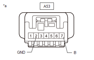
(a) Disconnect the A53 stop light switch assembly connector.
| (b) Measure the voltage according to the value(s) in the table below. Standard Voltage:
|
|
(c) Measure the resistance according to the value(s) in the table below.
Standard Resistance:
|
Tester Connection | Condition |
Specified Condition |
|---|---|---|
|
A53-2 (GND) - Body ground |
Always | Below 1 Ω |
| NG | | REPAIR OR REPLACE HARNESS OR CONNECTOR |
|
| 27. |
INSPECT STOP LIGHT SWITCH ASSEMBLY |
Click here
| NG | |
REPLACE STOP LIGHT SWITCH ASSEMBLY |
|
| 28. |
CHECK HARNESS AND CONNECTOR (CERTIFICATION ECU (SMART KEY ECU ASSEMBLY) - STOP LIGHT SWITCH ASSEMBLY) |
(a) Disconnect the I223 certification ECU (smart key ECU assembly) connector.
(b) Disconnect the A53 stop light switch assembly connector.
(c) Disconnect the A47 ECM connector.
(d) Disconnect the A151 skid control ECU (brake actuator assembly) connector.
(e) Disconnect the C80 transmission control ECU connector.
(f) Measure the resistance according to the value(s) in the table below.
Standard Resistance:
|
Tester Connection | Condition |
Specified Condition |
|---|---|---|
|
I223-21 (STP1) - A53-3 (L) |
Always | Below 1 Ω |
|
I223-21 (STP1) or A53-3 (L) - Other terminals and body ground |
Always | 10 kΩ or higher |
| OK | | REPLACE CERTIFICATION ECU (SMART KEY ECU ASSEMBLY) |
| NG | | REPAIR OR REPLACE HARNESS OR CONNECTOR |


