Toyota Corolla Cross: Electronic Brake Booster Control Module "A" Backup Power Supply Voltage System Voltage Low (C125DA2,C125DA3)
DESCRIPTION
The brake control power supply assembly is used as an auxiliary power supply for brake control when the voltage of the auxiliary battery is low.
|
DTC No. |
Detection Item |
DTC Detection Condition |
Trouble Area |
MIL |
DTC Output from |
Note |
|---|---|---|---|---|---|---|
|
C125DA2 |
Electronic Brake Booster Control Module "A" Backup Power Supply Voltage System Voltage Low |
Voltage from brake control power supply assembly is less than 2.8 V for 10 seconds. |
|
Does not come on |
Brake Booster |
Output ECU: Electric brake booster (brake booster with master cylinder assembly) |
|
C125DA3 |
Electronic Brake Booster Control Module "A" Backup Power Supply Voltage System Voltage High |
Brake control power supply assembly power source voltage is abnormal for 10 seconds or more. |
|
Does not come on |
Brake Booster |
Output ECU: Electric brake booster (brake booster with master cylinder assembly) |
WIRING DIAGRAM
Refer to DTC C121F87.
Click here .gif)
CAUTION / NOTICE / HINT
NOTICE:
Inspect the fuses for circuits related to this system before performing the following procedure.
PROCEDURE
|
1. |
CHECK HARNESS AND CONNECTOR (+BC TERMINAL) |
|
(a) Make sure that there is no looseness at the locking part and the connecting part of the connectors. OK: The connector is securely connected. |
|
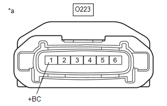
(b) Disconnect the O223 brake control power supply assembly connector.
(c) Check both the connector case and the terminals for deformation and corrosion.
OK:
No deformation or corrosion.
(d) Measure the voltage according to the value(s) in the table below.
Standard Voltage:
|
Tester Connection |
Condition |
Specified Condition |
|---|---|---|
|
O223-1 (+BC) - Body ground |
Always |
11 to 14 V |
| NG | .gif)
|
REPAIR OR REPLACE HARNESS OR CONNECTOR |
|
.gif)
|
2. |
CHECK HARNESS AND CONNECTOR (GND TERMINAL) |
(a) Make sure that there is no looseness at the locking part and the connecting part of the connectors.
OK:
The connector is securely connected.
(b) Disconnect the O223 brake control power supply assembly connector.
(c) Check both the connector case and the terminals for deformation and corrosion.
OK:
No deformation or corrosion.
(d) Measure the resistance according to the value(s) in the table below.
Standard Resistance:
|
Tester Connection |
Condition |
Specified Condition |
|---|---|---|
|
O223-4 (GND) - Body ground |
1 minute or more after disconnecting the cable from the negative (-) auxiliary battery terminal |
Below 1 Ω |
| NG |
|
REPAIR OR REPLACE HARNESS OR CONNECTOR |
|
|
3. |
CHECK HARNESS AND CONNECTOR (BRAKE BOOSTER WITH MASTER CYLINDER ASSEMBLY - BRAKE CONTROL POWER SUPPLY ASSEMBLY) |
(a) Make sure that there is no looseness at the locking part and the connecting part of the connectors.
OK:
The connector is securely connected.
(b) Disconnect the A189 electric brake booster (brake booster with master cylinder assembly) connector.
(c) Disconnect the O223 brake control power supply assembly connector.
(d) Check both the connector case and the terminals for deformation and corrosion.
OK:
No deformation or corrosion.
(e) Measure the resistance according to the value(s) in the table below.
Standard Resistance:
|
Tester Connection |
Condition |
Specified Condition |
|---|---|---|
|
A189-1 (CBKP) - O223-6 (OUT) |
Always |
Below 1 Ω |
|
A189-1 (CBKP) or O223-6 (OUT) - Body ground and other terminals |
Always |
10 kΩ or higher |
| OK |
|
REPLACE BRAKE BOOSTER WITH MASTER CYLINDER ASSEMBLY |
| NG |
|
REPAIR OR REPLACE HARNESS OR CONNECTOR |
READ NEXT:
 Electronic Brake Booster Input Stroke Sensor "A" Circuit Short to Ground (C127A11,...,C128F64)
DESCRIPTION
The relative displacement sensor is built into the brake booster
with master cylinder assembly.
When the relative displacement sensor inside the electric brake
booster (brake booster
Electronic Brake Booster Motor "A" Position Sensor Signal Cross Coupled (C129A2B,...,C136A1C)
DESCRIPTION
When the motor rotation angle sensor inside the electric brake
booster (brake booster with master cylinder assembly) meets the detection conditions,
this DTC is stored.
DT
Electronic Brake Booster System Mechanical Linkage Failure (C129F79)
DESCRIPTION
When the electric brake booster (brake booster with master cylinder
assembly) detects an abnormality with regard to system information that has already
been memorized, this DTC is sto
SEE MORE:
 Installation
INSTALLATION CAUTION / NOTICE / HINT COMPONENTS (INSTALLATION)
Procedure Part Name Code
1 OIL PRESSURE AND TEMPERATURE SENSOR
89448D
- -
2 INSPECT FOR ENGINE OIL LEAK
- -
- -
3 REAR ENGINE UNDER COVER R
Hybrid/EV Battery Current Sensor "A" Circuit Range/Performance (P0ABF00)
DESCRIPTION A battery current sensor, which is mounted on the positive cable side of each HV battery junction block assembly, detects the current flowing to or from the battery pack. The battery current sensor sends a voltage, which varies between 0 and 5 V in proportion to the amperage, to the IB0
