Toyota Corolla Cross: Driver Side Power Window Auto Up / Down Function does not Operate with Power Window Master Switch
DESCRIPTION
If the manual up and down functions operate normally but the auto up and down functions do not, the power window control system may be in fail-safe mode.
If power window initialization has not been performed, the auto up and down functions will not operate.
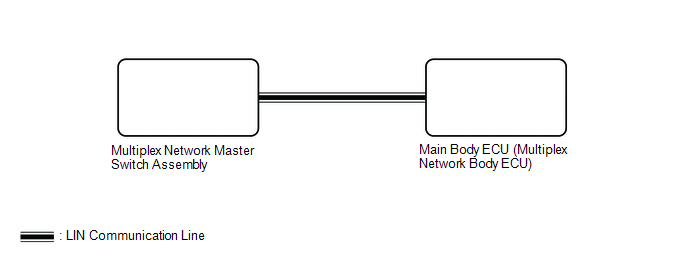
WIRING DIAGRAM
CAUTION / NOTICE / HINT
NOTICE:
- If the power window regulator motor assembly (for driver door) has been replaced with a new one, initialize the power window control system.
Click here
.gif)
- The power window control system uses the LIN communication system. Inspect the communication function by following How to Proceed with Troubleshooting. Troubleshoot the power window control system after confirming that the communication system is functioning properly.
Click here
- Check that power window system customize setting "D Window Auto Up Function" and "D Window Auto Down Function" are set to "Enable" before performing the following procedure.
Click here
- After the catch protection function has operated, the auto up function will not operate the first time the power window auto up switch is operated. The auto up function will operate normally after the first power window switch operation.
- Before replacing the main body ECU (multiplex network body ECU), refer to Registration.*1
- for HEV Model:
Click here
- for Gasoline Model:
Click here
- *1: w/ Smart Key System
- for HEV Model:
HINT:
If the pulse sensor built into the power window regulator motor assembly (for driver door) is malfunctioning, the power window control system will enter fail-safe mode. The remote up and down and auto up and down functions cannot be operated during fail-safe mode. However, the power window can be closed by holding the multiplex network master switch assembly at the auto up position, and opened manually by pushing down the multiplex network master switch assembly.
PROCEDURE
| 1. |
READ VALUE USING GTS |
(a) Read the Data List according to the display on the GTS.
Body Electrical > Master Switch > Data List|
Tester Display | Measurement Item |
Range | Normal Condition |
Diagnostic Note |
|---|---|---|---|---|
|
D Door P/W Auto SW | Driver door power window auto switch signal |
OFF or ON | OFF: Driver door power window auto up or auto down switch not being operated ON: Driver door power window auto up or auto down switch being operated |
- |
|
Tester Display |
|---|
| D Door P/W Auto SW |
OK:
On the GTS screen, ON or OFF is displayed accordingly.
| NG | .gif) | REPLACE MULTIPLEX NETWORK MASTER SWITCH ASSEMBLY |
|
.gif)
| 2. |
READ VALUE USING GTS |
(a) Read the Data List according to the display on the GTS.
Body Electrical > Main Body > Data List|
Tester Display | Measurement Item |
Range | Normal Condition |
Diagnostic Note |
|---|---|---|---|---|
|
D Door Power Window AUTO Switch |
Driver door power window auto switch |
OFF or ON | OFF: Auto up or auto down switch not being operated ON: Auto up or auto down switch being operated |
- |
|
Tester Display |
|---|
| D Door Power Window AUTO Switch |
OK:
On the GTS screen, ON or OFF is displayed accordingly.
| NG | | GO TO STEP 5 |
|
| 3. |
PERFORM INITIALIZATION |
(a) Initialize the power window regulator motor assembly (for driver door).
Click here
|
| 4. |
CHECK POWER WINDOW CONTROL SYSTEM (AUTO UP / DOWN FUNCTION) |
(a) Check that the driver door power window moves when the auto up and down functions of the multiplex network master switch assembly are operated.
Click here
OK:
Driver door auto up and down functions are normal.
| OK | | END (PROBLEM DUE TO INITIALIZATION FAILURE) |
| NG | | REPLACE POWER WINDOW REGULATOR MOTOR ASSEMBLY (for Driver Door) |
| 5. |
REPLACE MULTIPLEX NETWORK MASTER SWITCH ASSEMBLY |
(a) Replace the multiplex network master switch assembly.
Click here
|
| 6. |
CHECK POWER WINDOW CONTROL SYSTEM (AUTO UP / DOWN FUNCTION) |
(a) Check that the driver door power window moves when the auto up and down functions of the multiplex network master switch assembly are operated.
Click here
OK:
Driver door auto up and down functions are normal.
| OK | | END (MULTIPLEX NETWORK MASTER SWITCH ASSEMBLY WAS DEFECTIVE) |
| NG | | REPLACE MAIN BODY ECU (MULTIPLEX NETWORK BODY ECU) |
READ NEXT:
 Front Passenger Side Power Window Auto Up / Down Function does not Operate with Front Passenger Side Power Window Switch
DESCRIPTION If the manual up and down functions operate normally but the auto up and down functions do not, the power window control system may be in fail-safe mode.
If power window initialization ha
Rear Power Window LH Auto Up / Down Function does not Operate with Rear Power Window Switch LH
DESCRIPTION If the manual up and down functions operate normally but the auto up and down functions do not, the power window control system may be in fail-safe mode.
If power window initialization ha
Rear Power Window RH Auto Up / Down Function does not Operate with Rear Power Window Switch RH
DESCRIPTION If the manual up and down functions operate normally but the auto up and down functions do not, the power window control system may be in fail-safe mode.
If power window initialization ha
SEE MORE:
 Rear Floor 2 Electrical Key Oscillator Circuit Open (B27A713)
DESCRIPTION The certification ECU (smart key ECU assembly) generates a request signal and transmits the signal to the No. 3 indoor electrical key antenna assembly (inside luggage compartment). For the No. 3 indoor electrical key antenna assembly (inside luggage compartment) to detect when the electr
Security Indicator Light Does not Blink
DESCRIPTION
The certification ECU (smart key ECU assembly) blinks the security indicator light (air conditioning control assembly) when the immobiliser is set (ignition switch off).
The certification ECU (smart key ECU assembly) receives the security indicator light signal from the main bo
