Toyota Corolla Cross: Drive Start Control
DESCRIPTION
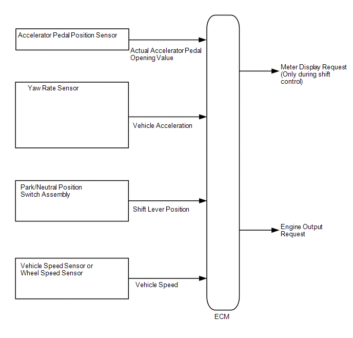
The drive start control is controlled by the ECM.
If the ECM determines that the shift lever and accelerator pedal are operated abnormally, engine output is restricted and, when necessary, a warning is displayed on the combination meter assembly.
CAUTION / NOTICE / HINT
HINT:
Even if the accelerator pedal position is maintained, the engine output may increase when driving uphill and decrease when driving downhill. This is due to the drive start control controlling the engine output, and is not a malfunction.
PROCEDURE
| 1. |
PAST ACTIVATION CONFIRMATION |
(a) Check if the customer operated the vehicle in a way that would cause the drive start control to operate.
- Pattern A (When all of the following conditions are met, control starts.)
- The accelerator pedal is open by approximately 1/5 or more.
- The shift lever is moved from P to any forward position D (other forward shift position) or R.
- Pattern B (When all of the following conditions are met, control starts.)
- The accelerator pedal is open by approximately 1/5 or more.
- The shift lever is moved from R to any forward position D (other forward shift position), any forward position D (other forward shift position) to R, or N to R.
HINT:
Operation may not be possible in certain situations.
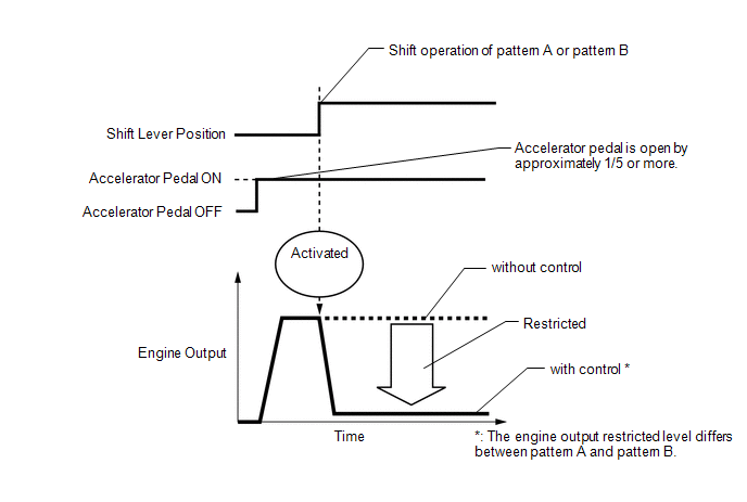
- Items Controlled
- Engine output is restricted.
- Deactivation Conditions
- The accelerator pedal is released.
- The shift lever is in P or N.
HINT:
- The restraint level for engine output differs for pattern A and pattern B.
- Engine output is corrected according to the slope incline when control is in operation.
- Control will not operate when TRC operation is stopped.
- Control will also not operate under the following conditions. (equipped models only)
- When in auto LSD mode
- When the transfer switch is operated to switch the status to L4
- When the center differential is locked
- When multi-terrain select is selected
|
Result | Proceed to |
|---|---|
|
Performed | A |
|
Not performed | B |
| B |
.gif) | SYSTEM NORMAL (GO TO PROBLEM SYMPTOM TABLE) |
|
.gif)
| 2. |
CHECK DTC OUTPUT (HEALTH CHECK) |
(a) Perform the Health Check using the GTS.
(b) Read the DTCs.
|
Result | Proceed to |
|---|---|
|
DTCs are not output (Hunting) |
A |
| DTCs are not output (Hesitation/poor acceleration) |
B |
| DTCs are output |
C |
| B |
| GO TO STEP 5 |
| C |
| GO TO DTC CHART |
|
| 3. |
READ VALUE USING GTS (FR, FL, RR, RL WHEEL SPEED) |
(a) Start the engine.
(b) Read the value displayed on the GTS.
Chassis > Brake/EPB > Data List|
Tester Display |
|---|
| FR Wheel Speed |
|
FL Wheel Speed |
| RR Wheel Speed |
|
RL Wheel Speed |
Standard:
|
GTS Display | Condition |
Specified Condition |
|---|---|---|
|
FR Wheel Speed FL Wheel Speed RR Wheel Speed RL Wheel Speed |
Vehicle stopped, engine running |
0 km/h (0 mph) |
|
Vehicle being driven at constant speed between 16.1 to 64.4 km/h (10 to 40 mph) |
No large fluctuations when driving at a constant speed |
CAUTION:
When performing a drive test, obey all speed limits and traffic laws.
HINT:
The data while driving can be stored by using the GTS data store function.
The stored data can be checked after driving.
| NG | | INSPECT FRONT OR REAR SPEED SENSOR |
|
| 4. |
READ VALUE USING GTS (FORWARD AND REARWARD G) |
(a) Start the engine.
(b) Read the value displayed on the GTS.
Chassis > Brake/EPB > Data List|
Tester Display |
|---|
| Forward and Rearward G |
Standard:
|
GTS Display | Condition |
Specified Condition |
|---|---|---|
|
Forward and Rearward G |
During deceleration | Value changes with vehicle speed |
|
During acceleration | Value changes with vehicle speed |
CAUTION:
When performing a drive test, obey all speed limits and traffic laws.
HINT:
The data while driving can be stored by using the GTS data store function.
The stored data can be checked after driving.
| OK | | SYSTEM NORMAL (GO TO PROBLEM SYMPTOM TABLE) |
| NG | | INSPECT AIRBAG ECU ASSEMBLY
|
| 5. |
INSPECT PARK/NEUTRAL POSITION SWITCH ASSEMBLY |
(a) Inspect the park/neutral position switch assembly.
for 2WD: Click here
.gif)
for AWD: Click here
|
Result | Proceed to |
|---|---|
|
Normal | A |
|
Abnormal | B |
| B |
| REPLACE PARK/NEUTRAL POSITION SWITCH ASSEMBLY for 2WD: Click here for AWD: Click here
|
|
| 6. |
READ VALUE USING GTS (ACCELERATOR POSITION SENSOR NO. 1 VOLTAGE % AND NO. 2 VOLTAGE %) |
(a) Turn the ignition switch to ON.
(b) Read the value displayed on the GTS.
Powertrain > Engine > Data List|
Tester Display |
|---|
| Accelerator Position Sensor No.1 Voltage % |
|
Accelerator Position Sensor No.2 Voltage % |
OK:
|
GTS Display | Condition |
Specified Condition |
|---|---|---|
|
Accelerator Position Sensor No.1 Voltage % |
Accelerator Pedal Released → Depressed |
Values smoothly change following accelerator pedal operation |
|
Accelerator Position Sensor No.2 Voltage % |
HINT:
For numerical values of Accelerator Position Sensor No.1 Voltage % and Accelerator Position Sensor No.2 Voltage %, refer to the Data List.
Click here
| OK | | SYSTEM NORMAL (GO TO PROBLEM SYMPTOM TABLE) |
| NG | | REPLACE ACCELERATOR PEDAL SENSOR ASSEMBLY |


