Toyota Corolla Cross: Disassembly
DISASSEMBLY
CAUTION / NOTICE / HINT
COMPONENTS (DISASSEMBLY)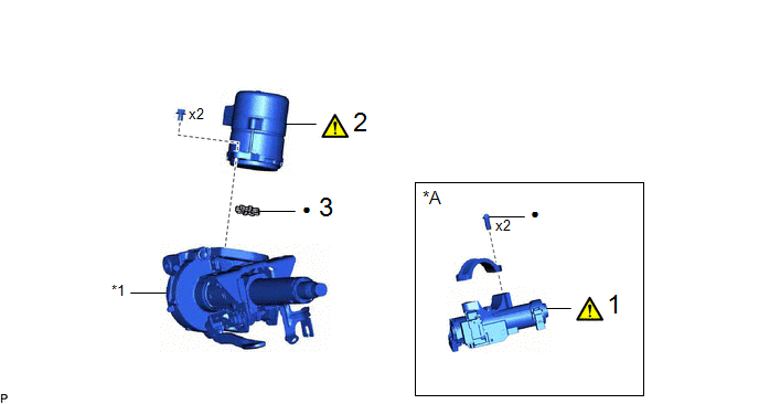
|
Procedure |
Part Name Code |
.png) |
.png) |
.png) |
|
|---|---|---|---|---|---|
|
1 |
UPPER STEERING COLUMN BRACKET WITH SWITCH ASSEMBLY |
45020 |
|
- |
- |
|
2 |
POWER STEERING ECU ASSEMBLY |
89650 |
|
- |
- |
|
3 |
ELECTRIC POWER STEERING MOTOR SHAFT DAMPER |
45254B |
- |
- |
- |
|
*A |
w/o Smart Key System |
- |
- |
|
*1 |
ELECTRIC POWER STEERING COLUMN SUB-ASSEMBLY |
- |
- |
|
● |
Non-reusable part |
- |
- |

|
Procedure |
Part Name Code |
|
|
|
|
|---|---|---|---|---|---|
|
4 |
IGNITION SWITCH LOCK CYLINDER ASSEMBLY |
- |
|
- |
- |
|
5 |
UN-LOCK WARNING SWITCH ASSEMBLY |
84052 |
|
- |
- |
|
6 |
IGNITION OR STARTER SWITCH ASSEMBLY |
84450 |
- |
- |
- |
|
*A |
w/o Smart Key System |
- |
- |
CAUTION / NOTICE / HINT
NOTICE:
- Do not drop the power steering ECU assembly, strike it with tools or subject it to impacts.
- If the power steering ECU assembly is subjected to an impact, replace it with a new one.
- Do not pull the wire harness.
- Do not allow any moisture to come into contact with the power steering ECU assembly.
- Do not loosen any bolts not mentioned in the procedure.
- Do not allow any foreign matter to contaminate the power steering ECU assembly.
PROCEDURE
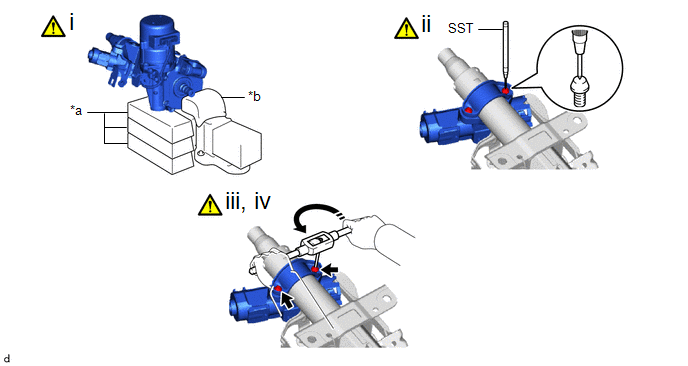
1. REMOVE UPPER STEERING COLUMN BRACKET WITH SWITCH ASSEMBLY (w/o Smart Key System)
|
*a |
Wooden Block |
*b |
Cloth |
 |
Turn |
- |
- |
(1) Secure the steering column assembly in a vise using aluminum plates, cloths and wooden blocks.
NOTICE:
- Do not overtighten the vise, as the steering column assembly may become deformed.
- Secure the power steering ECU assembly so that it is upright.
- Support the steering column assembly with wooden blocks or similar items to ensure that it does not fall.
(2) Using SST, strike a punch mark for drilling in the center of the steering lock set bolt.
SST: 09622-00010
NOTICE:
When striking the punch mark, in order to prevent impact force from being applied to the upper steering column bracket with switch assembly, do not use a normal center punch.
(3) Using a drill, drill a hole in the 2 steering lock set bolts and insert a screw extractor.
(4) Using the screw extractor, remove the 2 steering lock set bolts, upper steering column clamp and upper steering column bracket with switch assembly.
2. REMOVE POWER STEERING ECU ASSEMBLY
|
|
Click here |
3. REMOVE ELECTRIC POWER STEERING MOTOR SHAFT DAMPER
Click here .gif)
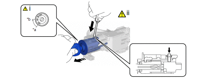
4. REMOVE IGNITION SWITCH LOCK CYLINDER ASSEMBLY (w/o Smart Key System)
|
*a |
LOCK |
*b |
ACC |
 |
Push |
|
Remove in this direction |
(1) Turn the ignition switch to ACC.
(2) Insert the tip of a screwdriver into the hole in the upper steering column bracket assembly to remove the ignition switch lock cylinder assembly as shown in the illustration.
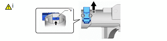
5. REMOVE UN-LOCK WARNING SWITCH ASSEMBLY (w/o Smart Key System)
|
*a |
Center Part |
- |
- |
|
|
Push |
|
Remove in this direction |
(1) Remove the un-lock warning switch assembly by pushing up the center part and releasing the claws.
6. REMOVE IGNITION OR STARTER SWITCH ASSEMBLY (w/o Smart Key System)