Toyota Corolla Cross: Disassembly
DISASSEMBLY
CAUTION / NOTICE / HINT
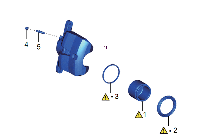
COMPONENTS (DISASSEMBLY)
|
Procedure |
Part Name Code |
.png) |
.png) |
.png) |
|
|---|---|---|---|---|---|
|
1 |
FRONT DISC BRAKE PISTON |
47731 |
|
- |
- |
|
2 |
CYLINDER BOOT |
- |
|
- |
- |
|
3 |
PISTON SEAL |
- |
|
- |
- |
|
4 |
FRONT DISC BRAKE BLEEDER PLUG CAP |
31478B |
- |
- |
- |
|
5 |
FRONT DISC BRAKE BLEEDER PLUG |
47547B |
- |
- |
- |
|
*1 |
FRONT DISC BRAKE CYLINDER |
- |
- |
|
● |
Non-reusable part |
- |
- |
PROCEDURE
1. REMOVE FRONT DISC BRAKE PISTON

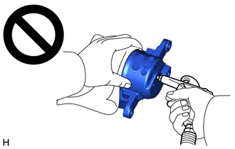
(1) Place a piece of cloth between the front disc brake piston and front disc brake cylinder.
(2) Apply compressed air to remove the front disc brake piston from the front disc brake cylinder.
CAUTION:
- Do not hold the front disc brake cylinder with any part of your hand
between the front disc brake cylinder and front disc brake piston.

- Do not place any part of your hand in front of the front disc brake piston when using compressed air as a severe injury may result.
NOTICE:
Do not allow any brake fluid to spatter.
2. REMOVE CYLINDER BOOT

(1) Using a screwdriver with its tip wrapped with protective tape, remove the cylinder boot from the front disc brake cylinder.
NOTICE:
Be careful not to damage the front disc brake cylinder.
3. REMOVE PISTON SEAL

(1) Using a screwdriver with its tip wrapped with protective tape, remove the piston seal from the front disc brake cylinder.
NOTICE:
Do not damage the inner surface or piston seal groove of the front disc brake cylinder.
4. REMOVE FRONT DISC BRAKE BLEEDER PLUG CAP

5. REMOVE FRONT DISC BRAKE BLEEDER PLUG


.gif)

