Toyota Corolla Cross: Crankshaft Position - Camshaft Position Correlation Bank 1 Sensor B (P001700)
DESCRIPTION
Refer to DTC P001313.
Click here
.gif)
|
DTC No. | Detection Item |
DTC Detection Condition | Trouble Area |
MIL | Note |
|---|---|---|---|---|---|
|
P001700 | Crankshaft Position - Camshaft Position Correlation Bank 1 Sensor B |
Deviation in the crankshaft position sensor signal and camshaft position sensor (for exhaust camshaft) signal (2 trip detection logic). |
| Comes on |
|
MONITOR DESCRIPTION
To monitor the correlation of the exhaust camshaft position and crankshaft position, the ECM checks the VVT learned value while the engine is idling. The VVT learned value is calibrated based on the camshaft position and crankshaft position. The exhaust valve timing is set to the most advanced angle while the engine is idling. If the VVT learned value is out of the specified range in consecutive driving cycles, the ECM illuminates the MIL and stores this DTC.
MONITOR STRATEGY
|
Related DTCs | P0017: Camshaft timing misalignment at idling (for exhaust camshaft) |
|
Required Sensors/Components (Main) | Camshaft timing exhaust gear assembly |
|
Required Sensors/Components (Related) |
Camshaft position sensor Crankshaft position sensor |
|
Frequency of Operation | Continuous |
|
Duration | Within 1 minute |
|
MIL Operation | 2 driving cycles |
|
Sequence of Operation | None |
TYPICAL ENABLING CONDITIONS
|
Monitor runs whenever the following DTCs are not stored |
None |
| Engine speed |
500 to 1000 rpm |
TYPICAL MALFUNCTION THRESHOLDS
|
Either of the following conditions is met |
A or B |
| A. VVT learned value at maximum advanced valve timing |
Less than 82.7°CA (Crankshaft Angle) |
|
B. VVT learned value at maximum advanced valve timing |
More than 105°CA (Crankshaft Angle) |
CONFIRMATION DRIVING PATTERN
HINT:
- After repair has been completed, clear the DTC and then check that the vehicle has returned to normal by performing the following All Readiness check procedure.
Click here
- When clearing the permanent DTCs, refer to the "CLEAR PERMANENT DTC" procedure.
Click here
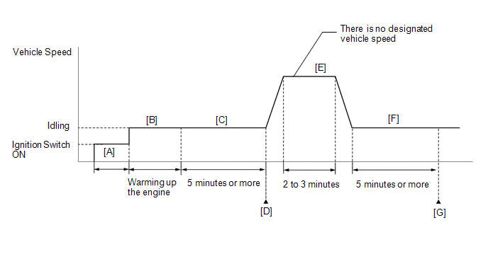
- Connect the GTS to the DLC3.
- Turn the ignition switch to ON.
- Turn the GTS on.
- Clear the DTCs (even if no DTCs are stored, perform the clear DTC procedure).
- Turn the ignition switch off and wait for at least 30 seconds.
- Turn the ignition switch to ON [A].
- Turn the GTS on.
- Start the engine and warm it up until the engine coolant temperature reaches 75°C (167°F) or higher [B].
- Idle the engine for 5 minutes or more [C].
- Enter the following menus: Powertrain / Engine / Trouble Codes [D].
- Read the pending DTCs.
HINT:
- If a pending DTC is output, the system is malfunctioning.
- If a pending DTC is not output, perform the following procedure.
- Enter the following menus: Powertrain / Engine / Utility / All Readiness.
- Input the DTC: P001700.
- Check the DTC judgment result.
GTS Display
Description
NORMAL
- DTC judgment completed
- System normal
ABNORMAL
- DTC judgment completed
- System abnormal
INCOMPLETE
- DTC judgment not completed
- Perform driving pattern after confirming DTC enabling conditions
HINT:
- If the judgment result is NORMAL, the system is normal.
- If the judgment result is ABNORMAL, the system has a malfunction.
- If the judgment result is INCOMPLETE, perform steps [E] through [G].
- [A] to [D]: Normal judgment procedure.
The normal judgment procedure is used to complete DTC judgment and also used when clearing permanent DTCs.
- When clearing the permanent DTCs, do not disconnect the cable from the auxiliary battery terminal or attempt to clear the DTCs during this procedure, as doing so will clear the universal trip and normal judgment histories.
- Drive the vehicle for 2 to 3 minutes [E].
CAUTION:
When performing the confirmation driving pattern, obey all speed limits and traffic laws.
- Idle the engine for 5 minutes or more [F].
- Enter the following menus: Powertrain / Engine / Trouble Codes [G].
- Read the pending DTCs.
HINT:
- If a pending DTC is output, the system is malfunctioning.
- If a pending DTC is not output, perform the following procedure.
- Check the DTC judgment result.
HINT:
- If the judgment result is NORMAL, the system is normal.
- If the judgment result is ABNORMAL, the system has a malfunction.
- [A] to [G]: Normal judgment procedure.
The normal judgment procedure is used to complete DTC judgment and also used when clearing permanent DTCs.
- When clearing the permanent DTCs, do not disconnect the cable from the auxiliary battery terminal or attempt to clear the DTCs during this procedure, as doing so will clear the universal trip and normal judgment histories.
CAUTION / NOTICE / HINT
HINT:
- The monitor for this DTC detects when the timing chain is shifted by one tooth or more (except Mexico Models).
- The monitor for this DTC detects when the timing chain is shifted by 2 to 3 teeth or more (for Mexico Models).
- Read Freeze Frame Data using the GTS. The ECM records vehicle and driving condition information as Freeze Frame Data the moment a DTC is stored. When troubleshooting, Freeze Frame Data can help determine if the vehicle was moving or stationary, if the engine was warmed up or not, if the air fuel ratio was lean or rich, and other data from the time the malfunction occurred.
PROCEDURE
|
1. | CHECK ANY OTHER DTCS OUTPUT (IN ADDITION TO DTC P001700) |
(a) Read the DTCs.
Powertrain > Engine > Trouble Codes|
Result | Proceed to |
|---|---|
|
DTC P001700 is output |
A |
| DTC P001700 and other DTCs are output |
B |
HINT:
If any DTCs other than P001700 are output, troubleshoot those DTCs first.
| B |
.gif) | GO TO DTC CHART |
|
.gif)
| 2. |
PERFORM ACTIVE TEST USING GTS (CONTROL THE EXHAUST VVT OCV DUTY RATIO BANK 1) |
HINT:
If the VVT system can be operated through the Active Test, it can be assumed that the VVT system is operating normally.
(a) Start the engine.
(b) Enter the following menus.
Powertrain > Engine > Active Test|
Active Test Display |
|---|
|
Control the Exhaust VVT OCV Duty Ratio Bank 1 |
|
Data List Display |
|---|
|
Exhaust VVT Change Angle Bank 1 |
(c) Perform the Active Test. Check that the displacement angle varies.
OK:
Displacement angle varies.
| NG | | GO TO STEP 4 |
|
| 3. |
CHECK ENGINE MECHANICAL SYSTEM |
(a) Check for mechanical malfunctions that affect the valve timing, such as a jumped tooth or stretching of the timing chain.
HINT:
Perform "Inspection After Repair" after repairing or replacing the engine mechanical system.
Click here
| OK | | GO TO STEP 7 |
| NG | | REPAIR OR REPLACE MALFUNCTIONING PARTS, COMPONENT AND AREA |
| 4. |
INSPECT CAM TIMING OIL CONTROL SOLENOID ASSEMBLY |
Click here
| NG | | REPLACE CAM TIMING OIL CONTROL SOLENOID ASSEMBLY |
|
| 5. |
INSPECT EXHAUST CAMSHAFT TIMING GEAR BOLT ASSEMBLY (CAMSHAFT TIMING OIL CONTROL VALVE ASSEMBLY) |
Click here
| NG | | REPLACE EXHAUST CAMSHAFT TIMING GEAR BOLT ASSEMBLY |
|
| 6. |
INSPECT CAMSHAFT TIMING EXHAUST GEAR ASSEMBLY |
(a) Inspect the camshaft timing exhaust gear assembly.
HINT:
Perform "Inspection After Repair" after replacing the camshaft timing exhaust gear assembly.
Click here
| NG | | REPLACE CAMSHAFT TIMING EXHAUST GEAR ASSEMBLY
|
|
| 7. |
CLEAR DTC |
(a) Clear the DTCs.
Powertrain > Engine > Clear DTCs(b) Turn the ignition switch off and wait for at least 30 seconds.
|
| 8. |
CHECK WHETHER DTC OUTPUT RECURS (DTC P001700) |
(a) Drive the vehicle in accordance with the driving pattern described in Confirmation Driving Pattern.
(b) Read the pending DTCs.
Powertrain > Engine > Trouble Codes|
Result | Proceed to |
|---|---|
|
DTCs are not output | A |
|
DTC P001700 is output |
B |
| A |
| CHECK FOR INTERMITTENT PROBLEMS |
| B |
| REPLACE ECM
|
READ NEXT:
 HO2S Heater Control Bank 1 Sensor 1 Circuit Short to Battery (P003012,P003013,P101A9E)
DESCRIPTION The air fuel ratio sensor (sensor 1) generates current that corresponds to the actual air fuel ratio. This sensor current is used to provide the ECM with feedback so that it can control th
HO2S Heater Control Circuit Bank 1 Sensor 2 Circuit Short to Battery (P003612,P003613,P102A9E)
DESCRIPTION The air fuel ratio sensor (sensor 2) generates current that corresponds to the actual air fuel ratio. This sensor current is used to provide the ECM with feedback so that it can control th
Fuel Rail / System Pressure - Too Low (P008700)
DESCRIPTION The high-pressure direct injection fuel system consists of a spill control valve, check valve, fuel relief valve, fuel pressure sensor (for high pressure side), fuel pump assembly (for hig
SEE MORE:
 Multi-axis Acceleration Sensor Module "A" Supply Voltage Circuit Voltage Out
of Range (C14D71C)
Multi-axis Acceleration Sensor Module "A" Supply Voltage Circuit Voltage Out
of Range (C14D71C)
DESCRIPTION
The airbag ECU assembly has a built-in yaw rate and acceleration
sensor and detects the vehicle condition.
This DTC is stored when the skid control ECU (brake actuator
assembly) receives a sensor supply voltage malfunction signal from the yaw rate
and acceleration sensor (airbag
Security Horn Circuit
DESCRIPTION When the theft deterrent system is switched from the armed state to the alarm sounding state, the main body ECU (multiplex network body ECU) transmits a signal to cause the security horn assembly to sound at intervals of 0.4 seconds. WIRING DIAGRAM
CAUTION / NOTICE / HINT
NOTICE:
