Toyota Corolla Cross: Multi-axis Acceleration Sensor Module "A" Supply Voltage Circuit Voltage Out of Range (C14D71C)
DESCRIPTION
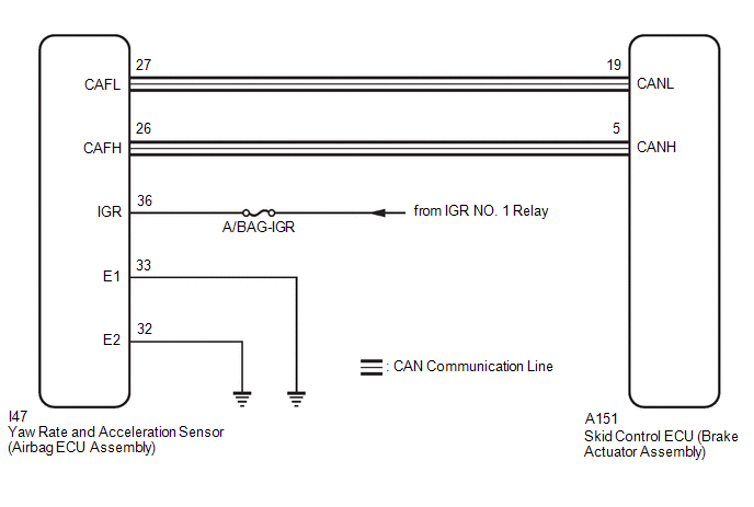
The airbag ECU assembly has a built-in yaw rate and acceleration sensor and detects the vehicle condition.
This DTC is stored when the skid control ECU (brake actuator assembly) receives a sensor supply voltage malfunction signal from the yaw rate and acceleration sensor (airbag ECU assembly).
|
DTC No. |
Detection Item |
DTC Detection Condition |
Trouble Area |
MIL |
DTC Output from |
Note |
|---|---|---|---|---|---|---|
|
C14D71C |
Multi-axis Acceleration Sensor Module "A" Supply Voltage Circuit Voltage Out of Range |
Vehicle speed is 6 km/h (4 mph) or more and yaw rate and acceleration sensor power supply malfunction signal is received for 1 second or more. |
|
Comes on |
Brake/EPB |
|
MONITOR DESCRIPTION
When the vehicle speed is a certain value or more, the power supply voltage of the skid control ECU (brake actuator assembly) is a certain value or more, CAN communication with the yaw rate and acceleration sensor (airbag ECU assembly) is valid, and a malfunction signal is received from the yaw rate sensor (airbag ECU assembly), the skid control ECU (brake actuator assembly) illuminates the MIL and stores this DTC.
MONITOR STRATEGY
|
Related DTCs |
C14D7: Yaw rate and acceleration sensor supply voltage failure (AWD) |
|
Required Sensors/Components(Main) |
Skid control ECU (brake actuator assembly) |
|
Required Sensors/Components(Related) |
Skid control ECU (brake actuator assembly) Speed sensor |
|
Frequency of Operation |
Continuous |
|
Duration |
1.1 seconds |
|
MIL Operation |
2 driving cycles |
|
Sequence of Operation |
None |
TYPICAL ENABLING CONDITIONS
|
Monitor runs whenever the following DTCs are not stored |
TMC's intellectual property |
|
Other conditions belong to TMC's intellectual property |
- |
TYPICAL MALFUNCTION THRESHOLDS
|
TMC's intellectual property |
- |
COMPONENT OPERATING RANGE
|
TMC's intellectual property |
- |
CONFIRMATION DRIVING PATTERN
NOTICE:
When performing the normal judgment procedure, make sure that the driver door is closed and is not opened at any time during the procedure.
HINT:
- After repair has been completed, clear the DTC and then check that the vehicle has returned to normal by performing the following All Readiness check procedure.
- When clearing the permanent DTCs, refer to the "CLEAR PERMANENT DTC" procedure.
- Connect the GTS to the DLC3.
- Turn the ignition switch to ON and turn the GTS on.
- Clear the DTCs (even if no DTCs are stored, perform the clear DTC procedure).
- Turn the ignition switch off.
- Turn the ignition switch to ON (READY) and turn the GTS on.
- Wait for 2 seconds or more. [*]
HINT:
[*]: Normal judgment procedure.
The normal judgment procedure is used to complete DTC judgment and also used when clearing permanent DTCs.
- Enter the following menus: Chassis / Brake/EPB* / Utility / All Readiness.
*: Electric Parking Brake System
- Check the DTC judgment result.
HINT:
- If the judgment result shows NORMAL, the system is normal.
- If the judgment result shows ABNORMAL, the system has a malfunction.
- If the judgment result shows INCOMPLETE, perform driving pattern again.
WIRING DIAGRAM
CAUTION / NOTICE / HINT
NOTICE:
- Inspect the fuses for circuits related to this system before performing the following procedure.
- When removing/installing a supplemental restraint systems related component,
disconnect the cable from the negative (-) auxiliary battery terminal before
performing the procedure.
Click here
.gif)
PROCEDURE
|
1. |
CHECK HARNESS AND CONNECTOR (POWER SOURCE TERMINAL) |
|
(a) Disconnect the cable from the negative (-) auxiliary battery terminal. CAUTION: Wait at least 60 seconds after disconnecting the cable from the negative (-) auxiliary battery terminal to disable the SRS system. Click here
|
|
.png)
(b) Make sure that there is no looseness at the locking part and the connecting part of the connector.
OK:
The connector is securely connected.
(c) Disconnect the I47 yaw rate and acceleration sensor (airbag ECU assembly) connector.
(d) Check both the connector case and the terminals for deformation and corrosion.
OK:
No deformation or corrosion.
(e) Connect the cable to the negative (-) auxiliary battery terminal.
(f) Turn the ignition switch to ON.
(g) Operate all the components of the electrical system (defogger, wipers, headlights, heater blower, etc.).
(h) Measure the voltage according to the value(s) in the table below.
Standard Voltage:
|
Tester Connection |
Condition |
Specified Condition |
|---|---|---|
|
I47-36 (IGR) - Body ground |
Ignition switch ON |
8 to 16 V |
| NG | .gif)
|
REPAIR OR REPLACE HARNESS OR CONNECTOR |
|
.gif)
|
2. |
CHECK HARNESS AND CONNECTOR (GROUND TERMINAL) |
(a) Turn the ignition switch off.
(b) Disconnect the cable from the negative (-) auxiliary battery terminal.
CAUTION:
Wait at least 60 seconds after disconnecting the cable from the negative (-) auxiliary battery terminal to disable the SRS system.
Click here
(c) Make sure that there is no looseness at the locking part and the connecting part of the connector.
OK:
The connector is securely connected.
(d) Disconnect the I47 yaw rate and acceleration sensor (airbag ECU assembly) connector.
(e) Check both the connector case and the terminals for deformation and corrosion.
OK:
No deformation or corrosion.
(f) Measure the resistance according to the value(s) in the table below.
Standard Resistance:
|
Tester Connection |
Condition |
Specified Condition |
|---|---|---|
|
I47-33 (E1) - Body ground |
1 minute or more after disconnecting the cable from the negative (-) auxiliary battery terminal |
Below 1 Ω |
|
I47-32 (E2) - Body ground |
1 minute or more after disconnecting the cable from the negative (-) auxiliary battery terminal |
Below 1 Ω |
| OK |
|
REPLACE AIRBAG ECU ASSEMBLY |
| NG |
|
REPAIR OR REPLACE HARNESS OR CONNECTOR |
READ NEXT:
 Left Front Wheel Speed Sensor Supply Voltage Circuit Short to Ground or Open
(C14E014)
Left Front Wheel Speed Sensor Supply Voltage Circuit Short to Ground or Open
(C14E014)
DESCRIPTION
Refer to DTC C050012
Click here
DTC No.
Detection Item
DTC Detection Condition
Trouble Area
MIL
DTC Output from
Right Front Wheel Speed Sensor Supply Voltage Circuit Short to Ground or Open
(C14E314)
DESCRIPTION
Refer to DTC C050612
Click here
DTC No.
Detection Item
DTC Detection Condition
Trouble Area
MIL
DTC Output from
Left Rear Wheel Speed Sensor Supply Voltage Circuit Short to Ground or Open
(C14E614)
DESCRIPTION
Refer to DTC C050C12
Click here
DTC No.
Detection Item
DTC Detection Condition
Trouble Area
MIL
DTC Output from
SEE MORE:
 Left Front Wheel Speed Sensor Incorrect Component Installed (C055595)
DESCRIPTION
DTC No.
Detection Item
DTC Detection Condition
Trouble Area
C055595
Left Front Wheel Speed Sensor Incorrect Component Installed
The front speed sensor LH is installed incorrectly.
Front speed s
Front Radar Sensor Optical Axis Misalignment Malfunction (C1A1100)
DESCRIPTION
The millimeter wave radar sensor assembly performs self-diagnosis
to check for misalignment of its beam axis. If misalignment is detected, the millimeter
wave radar sensor assembly stores DTC C1A1100.
DTC No.
Detection Item
DTC Detection Condition
