Toyota Corolla Cross: Crankshaft Position - Camshaft Position Correlation Bank 1 Sensor A (P001600)
DESCRIPTION
Refer to DTC P001001.
Click here
.gif)
|
DTC No. | Detection Item |
DTC Detection Condition | Trouble Area |
MIL | Note |
|---|---|---|---|---|---|
|
P001600 | Crankshaft Position - Camshaft Position Correlation Bank 1 Sensor A |
Deviation in the crankshaft position sensor signal and camshaft position sensor (for intake camshaft) signal (2 trip detection logic). |
| Comes on |
|
HINT:
If initialization is performed using the GTS with any of the connectors of the wire harnesses between the power source or ECM and the cam timing control motor with EDU assembly disconnected, DTC P001600 may be stored. If DTC P001600 is output, check the connection condition of each connector.
MONITOR DESCRIPTION
This DTC is stored when a deviation in the valve timing is detected. If a deviation in the valve timing is detected when the engine is idling (during valve timing learning) after performing learning value reset using the GTS or when the vehicle is being driven, the ECM determines that a malfunction has occurred. If a deviation in the valve timing is detected in consecutive driving cycles, the ECM stores a DTC.
In this case, DTC P03652A or P036531 (Camshaft Position Sensor [for Exhaust Camshaft] Malfunction) may also be stored.
MONITOR STRATEGY
|
Related DTCs | P0016: Camshaft timing misalignment at idling (for intake camshaft) |
|
Required Sensors/Components (Main) | Camshaft timing gear assembly |
|
Required Sensors/Components (Related) |
Camshaft position sensor Crankshaft position sensor |
|
Frequency of Operation | Continuous |
|
Duration | Within 1 minute |
|
MIL Operation | 2 driving cycles |
|
Sequence of Operation | None |
TYPICAL ENABLING CONDITIONS
|
Monitor runs whenever the following DTCs are not stored |
None |
| Engine speed |
500 to 1800 rpm |
TYPICAL MALFUNCTION THRESHOLDS
|
Either of the following conditions is met |
A or B |
| A. VVT learned value at maximum retarded valve timing |
Less than 22.2°CA (Crankshaft Angle) |
|
B. VVT learned value at maximum retarded valve timing |
More than 45.1°CA (Crankshaft Angle) |
CONFIRMATION DRIVING PATTERN
HINT:
- After repair has been completed, clear the DTC and then check that the vehicle has returned to normal by performing the following All Readiness check procedure.
Click here
- When clearing the permanent DTCs, refer to the "CLEAR PERMANENT DTC" procedure.
Click here
- Connect the GTS to the DLC3.
- Turn the ignition switch to ON.
- Turn the GTS on.
- Clear the DTCs (even if no DTCs are stored, perform the clear DTC procedure).
- Turn the ignition switch off and wait for at least 30 seconds.
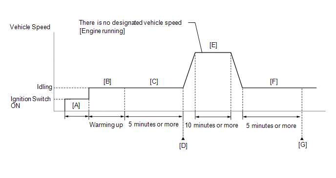
- Turn the ignition switch to ON [A].
- Turn the GTS on.
- Put the engine in Inspection Mode (Maintenance Mode).
Click here
- Start the engine and warm it up until the engine coolant temperature reaches 75°C (167°F) or higher [B].
- Idle the engine for 5 minutes or more [C].
- Enter the following menus: Powertrain / Engine / Trouble Codes [D].
- Read the pending DTCs.
HINT:
- If a pending DTC is output, the system is malfunctioning.
- If a pending DTC is not output, perform the following procedure.
- Enter the following menus: Powertrain / Engine / Utility / All Readiness.
- Input the DTC: P001600.
- Check the DTC judgment result.
GTS Display
Description
NORMAL
- DTC judgment completed
- System normal
ABNORMAL
- DTC judgment completed
- System abnormal
INCOMPLETE
- DTC judgment not completed
- Perform driving pattern after confirming DTC enabling conditions
HINT:
- If the judgment result is NORMAL, the system is normal.
- If the judgment result is ABNORMAL, the system has a malfunction.
- If the judgment result is INCOMPLETE, perform steps [E] through [G].
- [A] to [D]: Normal judgment procedure.
The normal judgment procedure is used to complete DTC judgment and also used when clearing permanent DTCs.
- When clearing the permanent DTCs, do not disconnect the cable from the auxiliary battery terminal or attempt to clear the DTCs during this procedure, as doing so will clear the universal trip and normal judgment histories.
- With the engine running, drive the vehicle for 10 minutes or more [E].
CAUTION:
When performing the confirmation driving pattern, obey all speed limits and traffic laws.
HINT:
If the engine stops, further depress the accelerator pedal to restart the engine.
- Idle the engine for 5 minutes or more [F].
- Enter the following menus: Powertrain / Engine / Trouble Codes [G].
- Read the pending DTCs.
HINT:
- If a pending DTC is output, the system is malfunctioning.
- If a pending DTC is not output, perform the following procedure.
- Check the DTC judgment result.
HINT:
- If the judgment result is NORMAL, the system is normal.
- If the judgment result is ABNORMAL, the system has a malfunction.
- [A] to [G]: Normal judgment procedure.
The normal judgment procedure is used to complete DTC judgment and also used when clearing permanent DTCs.
- When clearing the permanent DTCs, do not disconnect the cable from the auxiliary battery terminal or attempt to clear the DTCs during this procedure, as doing so will clear the universal trip and normal judgment histories.
CAUTION / NOTICE / HINT
NOTICE:
- Vehicle Control History may be stored in the hybrid vehicle control ECU assembly if the engine is malfunctioning. Certain vehicle condition information is recorded when Vehicle Control History is stored. Reading the vehicle conditions recorded in both the freeze frame data and Vehicle Control History can be useful for troubleshooting.
Click here
(Select Powertrain in Health Check and then check the time stamp data.)
- If any "Engine Malfunction" Vehicle Control History item has been stored in the hybrid vehicle control ECU assembly, make sure to clear it. However, as all Vehicle Control History items are cleared simultaneously, if any Vehicle Control History items other than "Engine Malfunction" are stored, make sure to perform any troubleshooting for them before clearing Vehicle Control History.
Click here
HINT:
Read Freeze Frame Data using the GTS. The ECM records vehicle and driving condition information as Freeze Frame Data the moment a DTC is stored. When troubleshooting, Freeze Frame Data can help determine if the vehicle was moving or stationary, if the engine was warmed up or not, if the air fuel ratio was lean or rich, and other data from the time the malfunction occurred.
PROCEDURE
| 1. |
CHECK ANY OTHER DTCS OUTPUT (IN ADDITION TO DTC P001600) |
(a) Read the DTCs.
Powertrain > Engine > Trouble Codes|
Result | Proceed to |
|---|---|
|
DTC P001600 is output |
A |
| DTC P001600 and other DTCs are output |
B |
HINT:
If any DTCs other than P001600 are output, troubleshoot those DTCs first.
| B |
.gif) | GO TO DTC CHART |
|
.gif)
| 2. |
INSPECT CAMSHAFT TIMING GEAR ASSEMBLY |
.png)
|
*1 | Camshaft Timing Gear Assembly |
|
*2 | Eccentric Shaft |
(a) Remove the cam timing control motor with EDU assembly.
Click here
(b) Check if the eccentric shaft of the camshaft timing gear assembly rotates smoothly.
NOTICE:
If the camshaft is at a position where a valve is about to open, the eccentric shaft may become difficult to rotate.
OK:
Rotates smoothly.
HINT:
Perform "Inspection After Repair" after replacing the camshaft timing gear assembly, or removing the cam timing control motor with EDU assembly.
Click here
| NG | | REPLACE CAMSHAFT TIMING GEAR ASSEMBLY |
|
| 3. |
CHECK VALVE TIMING (CHECK FOR LOOSE AND JUMPED TEETH ON TIMING CHAIN) |
.png)
|
*a | Timing Mark |
|
*b | TDC Timing Mark |
|
*c | Groove |
(a) Remove the cylinder head cover sub-assembly.
Click here
(b) Turn the crankshaft pulley and align its groove with the TDC timing mark of the timing chain cover.
(c) Check that the timing marks of the camshaft timing gear assembly and camshaft timing exhaust gear assembly are at the positions shown in the illustration.
HINT:
If the timing marks are not as shown, turn the crankshaft one revolution clockwise.
OK:
Timing marks on camshaft timing gear assembly and camshaft timing exhaust gear assembly are at the positions shown in the illustration.
HINT:
If the result is not as specified, check for mechanical malfunctions that may have affected the valve timing, such as a jumped tooth or stretching of the timing chain.
| NG | | REPAIR OR REPLACE MALFUNCTIONING PARTS, COMPONENT AND AREA |
|
| 4. |
CLEAR DTC |
(a) Clear the DTCs.
Powertrain > Engine > Clear DTCs(b) Turn the ignition switch off and wait for at least 30 seconds.
|
| 5. |
CHECK WHETHER DTC OUTPUT RECURS (DTC P001600) |
(a) Drive the vehicle in accordance with the driving pattern described in Confirmation Driving Pattern.
(b) Read the DTCs.
Powertrain > Engine > Trouble Codes|
Result | Proceed to |
|---|---|
|
DTCs are not output | A |
|
DTC P001600 is output |
B |
| A |
| CHECK FOR INTERMITTENT PROBLEMS |
| B |
| REPLACE ECM |
READ NEXT:
 Crankshaft Position - Camshaft Position Correlation Bank 1 Sensor B (P001700)
DESCRIPTION Refer to DTC P001313. Click here
DTC No. Detection Item
DTC Detection Condition Trouble Area
MIL Note
P001700 Crankshaft Position - Camshaft Position Co
HO2S Heater Control Bank 1 Sensor 1 Circuit Short to Battery (P003012,P003013,P101A9E)
DESCRIPTION The air fuel ratio sensor (sensor 1) generates current that corresponds to the actual air fuel ratio. This sensor current is used to provide the ECM with feedback so that it can control th
HO2S Heater Control Circuit Bank 1 Sensor 2 Circuit Short to Battery (P003612,P003613,P102A9E)
DESCRIPTION The air fuel ratio sensor (sensor 2) generates current that corresponds to the actual air fuel ratio. This sensor current is used to provide the ECM with feedback so that it can control th
SEE MORE:
 Door Control Switch (for Front Passenger Side)
RemovalREMOVAL CAUTION / NOTICE / HINT COMPONENTS (REMOVAL)
Procedure Part Name Code
1 POWER WINDOW REGULATOR SWITCH ASSEMBLY WITH FRONT DOOR ARMREST BASE UPPER PANEL RH
-
- -
2 DOOR CONTROL SWITCH ASSEMBLY
84930P
Replacement
REPLACEMENT
CAUTION / NOTICE / HINT
The necessary procedures (adjustment, calibration, initialization, or registration)
that must be performed after parts are removed and installed, or replaced during
the CVT fluid replacement are shown below.
Necessary Procedure After Parts Removed/Installed
