Toyota Corolla Cross Owners & Service Manuals

Toyota Corolla Cross: Check Mode Procedure

CHECK MODE PROCEDURE

HINT:

Compared to normal mode, check mode is more sensitive to malfunctions. Therefore, check mode can detect malfunctions that cannot be detected in normal mode.

NOTICE:

All of the stored DTCs and Freeze Frame Data are cleared if: 1) the ECM is changed from normal mode to check mode or vice versa; or 2) the ignition switch is turned from ON to ACC or off while in check mode. Before changing modes, always check for and note any DTCs and Freeze Frame Data.

CHECK MODE PROCEDURE

(a) Check and ensure the following conditions:

(1) Auxiliary battery voltage is 11 V or higher.

(2) Accelerator pedal fully released.

(3) Shift lever is in P or N.

(4) A/C switch is off.

(b) Turn the ignition switch off.

(c) Connect the GTS to the DLC3.

(d) Turn the ignition switch to ON.

(e) Turn the GTS on.

(f) Enter the following menus: Powertrain / Engine / Utility / Check Mode.

Powertrain > Engine > Utility

Tester Display

Check Mode

(g) Change the ECM from normal mode to check mode.

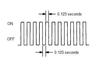
(h) Check that the MIL flashes as shown in the illustration.

(i) Start the engine.

(j) Check that the MIL turns off.

(k) Simulate the conditions of the malfunction described by the customer.

(l) Check for DTCs and Freeze Frame Data using the GTS.

    READ NEXT:

     Fail-safe Chart

    FAIL-SAFE CHART If any of the following DTCs are stored, the ECM enters fail-safe mode to allow the vehicle to be driven temporarily or stops fuel injection. DTC Code Component Fail-Safe

     Data List / Active Test

    DATA LIST / ACTIVE TEST DATA LIST HINT: Using the GTS to read the Data List allows the values or states of switches, sensors, actuators and other items to be read without removing any parts. This no

     Diagnostic Trouble Code Chart

    DIAGNOSTIC TROUBLE CODE CHART SFI System DTC No. Detection Item MIL Note Link P001001 Camshaft Position "A" Actuator Bank 1 General Electrical Failure Comes on

    SEE MORE:

     Parts Location

    PARTS LOCATION ILLUSTRATION *A w/ Power Back Door System - - *1 FRONT DOOR LOCK WITH MOTOR ASSEMBLY LH *2 FRONT DOOR LOCK WITH MOTOR ASSEMBLY RH *3 REAR DOOR LOCK WITH MOTOR ASSEMBLY LH *4 REAR DOOR LOCK WITH MOTOR ASSEMBLY RH *5 FRON

     Using an anchor bracket (for top tether strap) (except for Puerto Rico)

    ■ Anchor brackets (for top tether strap) Anchor brackets are provided for each rear seat. Use anchor brackets when fixing the top tether strap. Anchor brackets Top tether strap ■ Fixing the top tether strap to the anchor bracket Install the child restraint system in accordance to the opera

    © 2020-2024 Copyright www.tcorollacross.com