Toyota Corolla Cross: Check Bus 2 Line
DESCRIPTION
|
Symptom |
Trouble Area |
|---|---|
|
There are ECUs or sensors that display a communication stop on the bus diagnostic screen. Or, there are ECUs or sensors that display communication stop history on the "Detail" screen. |
|
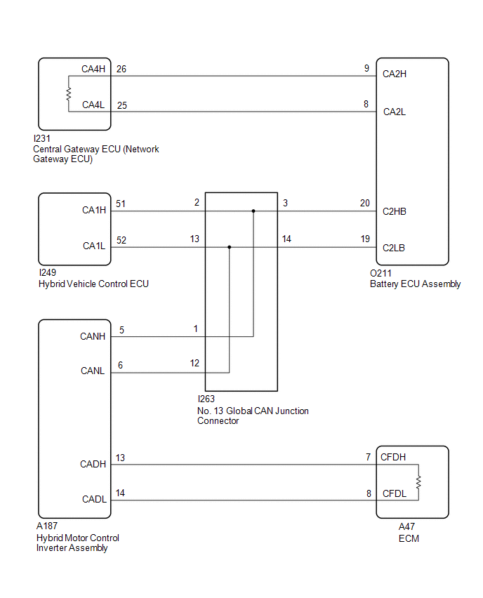
WIRING DIAGRAM
CAUTION / NOTICE / HINT
CAUTION:
- When performing the confirmation driving pattern, obey all speed limits and traffic laws.
- Before the following operations are conducted, take precautions to prevent
electric shock by turning the power switch off, wearing insulated gloves, and
removing the service plug grip from HV battery.
.png)
- Inspecting the high-voltage system
- Disconnecting the low voltage connector of the hybrid motor control inverter assembly
- Disconnecting the low voltage connector of the HV battery
- To prevent electric shock, make sure to remove the service plug grip to
cut off the high voltage circuit before servicing the vehicle.
.png)
- After removing the service plug grip from the HV battery, put it in your
pocket to prevent other technicians from accidentally reconnecting it while
you are working on the high-voltage system.
.png)
- After removing the service plug grip, wait for at least 10 minutes before
touching any of the high-voltage connectors or terminals. After waiting for
10 minutes, check the voltage at the terminals in the inspection point in the
hybrid motor control inverter assembly. The voltage should be 0 V before beginning
work.
Click here
.gif)
HINT:
Waiting for at least 10 minutes is required to discharge the high-voltage capacitor inside the hybrid motor control inverter assembly.
.png)
*a
Without waiting for 10 minutes
NOTICE:
- Because the order of diagnosis is important to allow correct diagnosis,
make sure to begin troubleshooting using How to Proceed with Troubleshooting
when CAN communication system related DTCs are output.
Click here
- Before measuring the resistance of the CAN bus, turn the ignition switch off and leave the vehicle for 1 minute or more without operating the key or any switches, or opening or closing the doors. After that, disconnect the cable from the negative (-) auxiliary battery terminal and leave the vehicle for 1 minute or more before measuring the resistance.
- After the ignition switch is turned off, there may be a waiting time before
disconnecting the negative (-) auxiliary battery terminal.
Click here
- When disconnecting and reconnecting the auxiliary battery.
HINT:
When disconnecting and reconnecting the auxiliary battery, there is an automatic learning function that completes learning when the respective system is used.
Click here
- Some parts must be initialized and set when replacing or removing and installing
parts.
Click here
- After performing repairs, perform the DTC check procedure and confirm that
the DTCs are not output again.
DTC check procedure: Turn the ignition switch to ON and wait for 1 minute or more. Then operate the suspected malfunctioning system and drive the vehicle at 60 km/h (37 mph) or more for 5 minutes or more.
- After the repair, perform the CAN bus check and check that all the ECUs
and sensors connected to the CAN communication system are displayed as normal.
Click here
- Before replacing the hybrid vehicle control ECU, refer to Registration.
Click here
HINT:
- Before disconnecting related connectors for inspection, push in on each connector body to check that the connector is not loose or disconnected.
- When a connector is disconnected, check that the terminals and connector body are not cracked, deformed or corroded.
PROCEDURE
|
1. |
CHECK FOR OPEN IN CAN MAIN BUS LINES |
(a) Disconnect the cable from the negative (-) auxiliary battery terminal.
|
(b) Measure the resistance according to the value(s) in the table below. Standard Resistance:
|
|
| NG | .gif) |
GO TO STEP 35 |
|
.gif)
|
2. |
CHECK FOR SHORT IN CAN BUS LINES |
|
(a) Measure the resistance according to the value(s) in the table below. Standard Resistance:
|
|
| NG | |
GO TO STEP 25 |
|
|
3. |
CHECK FOR SHORT TO +B IN CAN BUS LINE |
(a) Measure the resistance according to the value(s) in the table below.
|
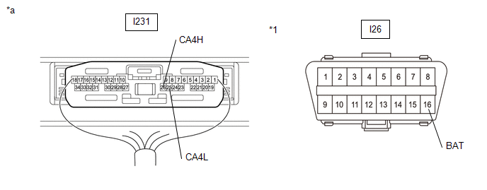
*1 |
DLC3 |
- |
- |
|
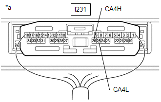
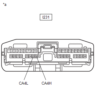
*a |
Component with harness connected (Central Gateway ECU (Network Gateway ECU)) |
- |
- |
Standard Resistance:
|
Tester Connection |
Condition |
Specified Condition |
|---|---|---|
|
I231-26 (CA4H) - I26-16 (BAT) |
Cable disconnected from negative (-) auxiliary battery terminal |
6 kΩ or higher |
|
I231-25 (CA4L) - I26-16 (BAT) |
| NG | |
GO TO STEP 15 |
|
|
4. |
CHECK FOR SHORT TO GND IN CAN BUS LINE |
(a) Measure the resistance according to the value(s) in the table below.
|
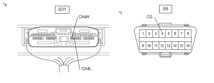
*1 |
DLC3 |
- |
- |
|
*a |
Component with harness connected (Central Gateway ECU (Network Gateway ECU)) |
- |
- |
Standard Resistance:
|
Tester Connection |
Condition |
Specified Condition |
|---|---|---|
|
I231-26 (CA4H) - I26-4 (CG) |
Cable disconnected from negative (-) auxiliary battery terminal |
200 Ω or higher |
|
I231-25 (CA4L) - I26-4 (CG) |
| OK | |
REPLACE CENTRAL GATEWAY ECU (NETWORK GATEWAY ECU) |
|
|
5. |
CHECK FOR SHORT TO GND IN CAN BUS LINE (BATTERY ECU ASSEMBLY - CENTRAL GATEWAY ECU (NETWORK GATEWAY ECU)) |
CAUTION:
Be sure to wear insulated gloves.
(a) Check that the service plug grip is not installed.
NOTICE:
After removing the service plug grip, do not turn the ignition switch to ON (READY), unless instructed by the repair manual because this may cause a malfunction.
(b) Disconnect the battery ECU assembly connector.
(c) Measure the resistance according to the value(s) in the table below.
|
*1 |
DLC3 |
- |
- |
|
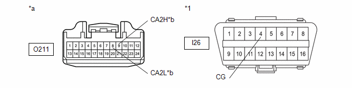
*a |
Front view of wire harness connector (to Battery ECU Assembly) |
*b |
to Central Gateway ECU (Network Gateway ECU) |
Standard Resistance:
|
Tester Connection |
Condition |
Specified Condition |
|---|---|---|
|
O211-9 (CA2H) - I26-4 (CG) |
Cable disconnected from negative (-) auxiliary battery terminal |
200 Ω or higher |
|
O211-8 (CA2L) - I26-4 (CG) |
| NG | |
GO TO STEP 7 |
|
|
6. |
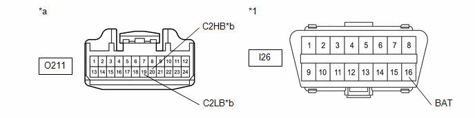
CHECK FOR SHORT TO GND IN CAN BUS LINE (BATTERY ECU ASSEMBLY - NO. 13 GLOBAL CAN JUNCTION CONNECTOR) |
(a) Measure the resistance according to the value(s) in the table below.
|
*1 |
DLC3 |
- |
- |
|
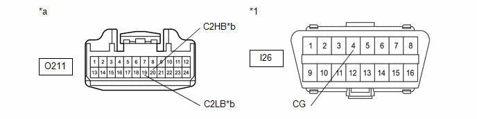
*a |
Front view of wire harness connector (to Battery ECU Assembly) |
*b |
to No. 13 Global CAN Junction Connector |
Standard Resistance:
|
Tester Connection |
Condition |
Specified Condition |
|---|---|---|
|
O211-20 (C2HB) - I26-4 (CG) |
Cable disconnected from negative (-) auxiliary battery terminal |
200 Ω or higher |
|
O211-19 (C2LB) - I26-4 (CG) |
| OK | |
REPLACE BATTERY ECU ASSEMBLY |
| NG | |
GO TO STEP 8 |
|
7. |
CHECK FOR SHORT TO GND IN CAN BUS LINE (BATTERY ECU ASSEMBLY - CENTRAL GATEWAY ECU (NETWORK GATEWAY ECU)) |
(a) Disconnect the I231 central gateway ECU (network gateway ECU) connector.
(b) Measure the resistance according to the value(s) in the table below.
|
*1 |
DLC3 |
- |
- |
|
*a |
Front view of wire harness connector (to Battery ECU Assembly) |
*b |
to Central Gateway ECU (Network Gateway ECU) |
Standard Resistance:
|
Tester Connection |
Condition |
Specified Condition |
|---|---|---|
|
O211-9 (CA2H) - I26-4 (CG) |
Cable disconnected from negative (-) auxiliary battery terminal |
200 Ω or higher |
|
O211-8 (CA2L) - I26-4 (CG) |
| OK | |
REPLACE CENTRAL GATEWAY ECU (NETWORK GATEWAY ECU) |
| NG | |
REPAIR OR REPLACE CAN MAIN BUS LINE OR CONNECTOR (BATTERY ECU ASSEMBLY - CENTRAL GATEWAY ECU (NETWORK GATEWAY ECU)) |
|
8. |
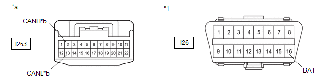
CHECK FOR SHORT TO GND IN CAN BUS LINE (NO. 13 GLOBAL CAN JUNCTION CONNECTOR - BATTERY ECU ASSEMBLY) |
(a) Disconnect the No. 13 global CAN junction connector.
(b) Measure the resistance according to the value(s) in the table below.
|
*1 |
DLC3 |
- |
- |
|
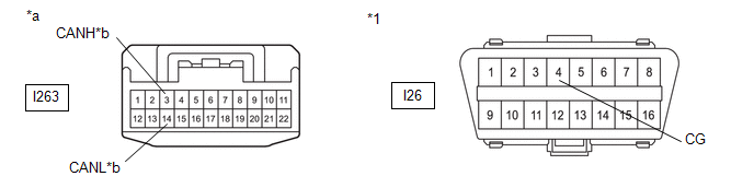
*a |
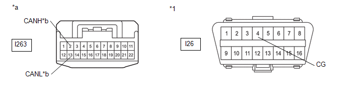
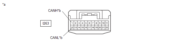
Front view of wire harness connector (to No. 13 Global CAN Junction Connector) |
*b |
to Battery ECU Assembly |
Standard Resistance:
|
Tester Connection |
Condition |
Specified Condition |
|---|---|---|
|
I263-3 (CANH) - I26-4 (CG) |
Cable disconnected from negative (-) auxiliary battery terminal |
200 Ω or higher |
|
I263-14 (CANL) - I26-4 (CG) |
| NG | |
REPAIR OR REPLACE CAN MAIN BUS LINE OR CONNECTOR (NO. 13 GLOBAL CAN JUNCTION CONNECTOR - BATTERY ECU ASSEMBLY) |
|
|
9. |
CHECK FOR SHORT TO GND IN CAN BUS LINE (NO. 13 GLOBAL CAN JUNCTION CONNECTOR - HYBRID MOTOR CONTROL INVERTER ASSEMBLY) |
(a) Measure the resistance according to the value(s) in the table below.
|
*1 |
DLC3 |
- |
- |
|
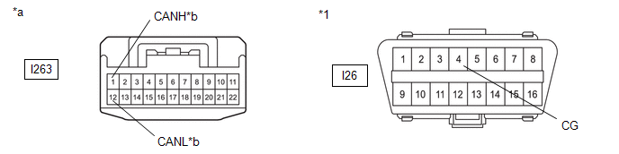
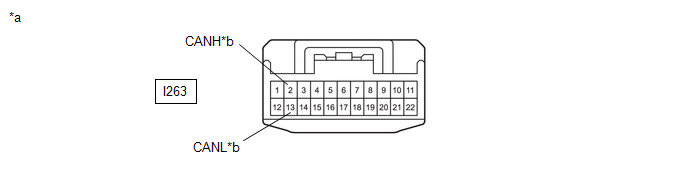
*a |
Front view of wire harness connector (to No. 13 Global CAN Junction Connector) |
*b |
to Hybrid Motor Control Inverter Assembly |
Standard Resistance:
|
Tester Connection |
Condition |
Specified Condition |
|---|---|---|
|
I263-1 (CANH) - I26-4 (CG) |
Cable disconnected from negative (-) auxiliary battery terminal |
200 Ω or higher |
|
I263-12 (CANL) - I26-4 (CG) |
| NG | |
GO TO STEP 12 |
|
|
10. |
CHECK FOR SHORT TO GND IN CAN BUS LINE (NO. 13 GLOBAL CAN JUNCTION CONNECTOR - HYBRID VEHICLE CONTROL ECU) |
(a) Measure the resistance according to the value(s) in the table below.
|
*1 |
DLC3 |
- |
- |
|
*a |
Front view of wire harness connector (to No. 13 Global CAN Junction Connector) |
*b |
to Hybrid Vehicle Control ECU |
Standard Resistance:
|
Tester Connection |
Condition |
Specified Condition |
|---|---|---|
|
I263-13 (CANL) - I26-4 (CG) |
Cable disconnected from negative (-) auxiliary battery terminal |
200 Ω or higher |
|
I263-13 (CANL) - I26-4 (CG) |
| OK | |
REPLACE NO. 13 GLOBAL CAN JUNCTION CONNECTOR |
|
|
11. |
CHECK FOR SHORT TO GND IN CAN BUS LINE (NO. 13 GLOBAL CAN JUNCTION CONNECTOR - HYBRID VEHICLE CONTROL ECU) |
(a) Disconnect the I249 hybrid vehicle control ECU connector.
(b) Measure the resistance according to the value(s) in the table below.
|
*1 |
DLC3 |
- |
- |
|
*a |
Front view of wire harness connector (to No. 13 Global CAN Junction Connector) |
*b |
to Hybrid Vehicle Control ECU |
Standard Resistance:
|
Tester Connection |
Condition |
Specified Condition |
|---|---|---|
|
I263-2 (CANH) - I26-4 (CG) |
Cable disconnected from negative (-) auxiliary battery terminal |
200 Ω or higher |
|
I263-13 (CANL) - I26-4 (CG) |
| OK | |
REPLACE HYBRID VEHICLE CONTROL ECU |
| NG | |
REPAIR OR REPLACE CAN BRANCH LINE OR CONNECTOR (NO. 13 GLOBAL CAN JUNCTION CONNECTOR - HYBRID VEHICLE CONTROL ECU) |
|
12. |
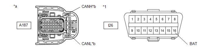
CHECK FOR SHORT TO GND IN CAN BUS LINE (HYBRID MOTOR CONTROL INVERTER ASSEMBLY - NO. 13 GLOBAL CAN JUNCTION CONNECTOR) |
CAUTION:
Be sure to wear insulated gloves.
(a) Check that the service plug grip is not installed.
NOTICE:
After removing the service plug grip, do not turn the ignition switch to ON (READY), unless instructed by the repair manual because this may cause a malfunction.
(b) Disconnect the hybrid motor control inverter assembly connector.
(c) Measure the resistance according to the value(s) in the table below.
|
*1 |
DLC3 |
- |
- |
|
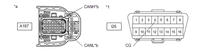
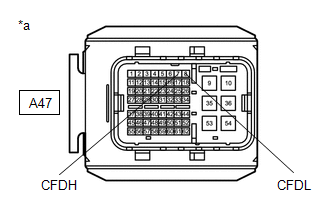
*a |
Front view of wire harness connector (to Hybrid Motor Control Inverter Assembly) |
*b |
to No. 13 Global CAN Junction Connector |
Standard Resistance:
|
Tester Connection |
Condition |
Specified Condition |
|---|---|---|
|
A187-5 (CANH) - I26-4 (CG) |
Cable disconnected from negative (-) auxiliary battery terminal |
200 Ω or higher |
|
A187-6 (CANL) - I26-4 (CG) |
| NG | |
REPAIR OR REPLACE CAN MAIN BUS LINE OR CONNECTOR (HYBRID MOTOR CONTROL INVERTER ASSEMBLY - NO. 13 GLOBAL CAN JUNCTION CONNECTOR) |
|
|
13. |
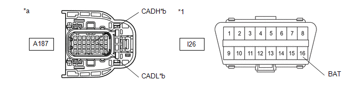
CHECK FOR SHORT TO GND IN CAN BUS LINE (HYBRID MOTOR CONTROL INVERTER ASSEMBLY - ECM) |
(a) Measure the resistance according to the value(s) in the table below.
|
*1 |
DLC3 |
- |
- |
|
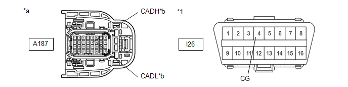
*a |
Front view of wire harness connector (to Hybrid Motor Control Inverter Assembly) |
*b |
to ECM |
Standard Resistance:
|
Tester Connection |
Condition |
Specified Condition |
|---|---|---|
|
A187-13 (CADH) - I26-4 (CG) |
Cable disconnected from negative (-) auxiliary battery terminal |
200 Ω or higher |
|
A187-14 (CADL) - I26-4 (CG) |
| OK | |
REPLACE MG ECU (REPLACE HYBRID MOTOR CONTROL INVERTER ASSEMBLY) |
|
|
14. |
CHECK FOR SHORT TO GND IN CAN BUS LINE (HYBRID MOTOR CONTROL INVERTER ASSEMBLY - ECM) |
(a) Disconnect the A47 ECM connector.
(b) Measure the resistance according to the value(s) in the table below.
|
*1 |
DLC3 |
- |
- |
|
*a |
Front view of wire harness connector (to Hybrid Motor Control Inverter Assembly) |
*b |
to ECM |
Standard Resistance:
|
Tester Connection |
Condition |
Specified Condition |
|---|---|---|
|
A187-13 (CADH) - I26-4 (CG) |
Cable disconnected from negative (-) auxiliary battery terminal |
200 Ω or higher |
|
A187-14 (CADL) - I26-4 (CG) |
| OK | |
REPLACE ECM |
| NG | |
REPAIR OR REPLACE CAN MAIN BUS LINE OR CONNECTOR (HYBRID MOTOR CONTROL INVERTER ASSEMBLY - ECM) |
|
15. |
CHECK FOR SHORT TO +B IN CAN BUS LINE (BATTERY ECU ASSEMBLY - CENTRAL GATEWAY ECU (NETWORK GATEWAY ECU)) |
CAUTION:
Be sure to wear insulated gloves.
(a) Check that the service plug grip is not installed.
NOTICE:
After removing the service plug grip, do not turn the ignition switch to ON (READY), unless instructed by the repair manual because this may cause a malfunction.
(b) Disconnect the battery ECU assembly connector.
(c) Measure the resistance according to the value(s) in the table below.
|
*1 |
DLC3 |
- |
- |
|
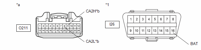
*a |
Front view of wire harness connector (to Battery ECU Assembly) |
*b |
to Central Gateway ECU (Network Gateway ECU) |
Standard Resistance:
|
Tester Connection |
Condition |
Specified Condition |
|---|---|---|
|
O211-9 (CA2H) - I26-16 (BAT) |
Cable disconnected from negative (-) auxiliary battery terminal |
6 kΩ or higher |
|
O211-8 (CA2L) - I26-16 (BAT) |
| NG | |
GO TO STEP 17 |
|
|
16. |
CHECK FOR SHORT TO +B IN CAN BUS LINE (BATTERY ECU ASSEMBLY - NO. 13 GLOBAL CAN JUNCTION CONNECTOR) |
(a) Measure the resistance according to the value(s) in the table below.
|
*1 |
DLC3 |
- |
- |
|
*a |
Front view of wire harness connector (to Battery ECU Assembly) |
*b |
to No. 13 Global CAN Junction Connector |
Standard Resistance:
|
Tester Connection |
Condition |
Specified Condition |
|---|---|---|
|
O211-20 (C2HB) - I26-16 (BAT) |
Cable disconnected from negative (-) auxiliary battery terminal |
6 kΩ or higher |
|
O211-19 (C2LB) - I26-16 (BAT) |
| OK | |
REPLACE BATTERY ECU ASSEMBLY |
| NG | |
GO TO STEP 18 |
|
17. |
CHECK FOR SHORT TO +B IN CAN BUS LINE (BATTERY ECU ASSEMBLY - CENTRAL GATEWAY ECU (NETWORK GATEWAY ECU)) |
(a) Disconnect the I231 central gateway ECU (network gateway ECU) connector.
(b) Measure the resistance according to the value(s) in the table below.
|
*1 |
DLC3 |
- |
- |
|
*a |
Front view of wire harness connector (to Battery ECU Assembly) |
*b |
to Central Gateway ECU (Network Gateway ECU) |
Standard Resistance:
|
Tester Connection |
Condition |
Specified Condition |
|---|---|---|
|
O211-9 (CA2H) - I26-16 (BAT) |
Cable disconnected from negative (-) auxiliary battery terminal |
6 kΩ or higher |
|
O211-8 (CA2L) - I26-16 (BAT) |
| OK | |
REPLACE CENTRAL GATEWAY ECU (NETWORK GATEWAY ECU) |
| NG | |
REPAIR OR REPLACE CAN MAIN BUS LINE OR CONNECTOR (BATTERY ECU ASSEMBLY - CENTRAL GATEWAY ECU (NETWORK GATEWAY ECU)) |
|
18. |
CHECK FOR SHORT TO +B IN CAN BUS LINE (NO. 13 GLOBAL CAN JUNCTION CONNECTOR - BATTERY ECU ASSEMBLY) |
(a) Disconnect the No. 13 global CAN junction connector.
(b) Measure the resistance according to the value(s) in the table below.

|
*1 |
DLC3 |
- |
- |
|
*a |
Front view of wire harness connector (to No. 13 Global CAN Junction Connector) |
*b |
to Battery ECU Assembly |
Standard Resistance:
|
Tester Connection |
Condition |
Specified Condition |
|---|---|---|
|
I263-3 (CANH) - I26-16 (BAT) |
Cable disconnected from negative (-) auxiliary battery terminal |
6 kΩ or higher |
|
I263-14 (CANL) - I26-16 (BAT) |
| NG | |
REPAIR OR REPLACE CAN MAIN BUS LINE OR CONNECTOR (NO. 13 GLOBAL CAN JUNCTION CONNECTOR - BATTERY ECU ASSEMBLY) |
|
|
19. |
CHECK FOR SHORT TO +B IN CAN BUS LINE (NO. 13 GLOBAL CAN JUNCTION CONNECTOR - HYBRID MOTOR CONTROL INVERTER ASSEMBLY) |
(a) Measure the resistance according to the value(s) in the table below.

|
*1 |
DLC3 |
- |
- |
|
*a |
Front view of wire harness connector (to No. 13 Global CAN Junction Connector) |
*b |
to Hybrid Motor Control Inverter Assembly |
Standard Resistance:
|
Tester Connection |
Condition |
Specified Condition |
|---|---|---|
|
I263-1 (CANH) - I26-16 (BAT) |
Cable disconnected from negative (-) auxiliary battery terminal |
6 kΩ or higher |
|
I263-12 (CANL) - I26-16 (BAT) |
| NG | |
GO TO STEP 22 |
|
|
20. |
CHECK FOR SHORT TO +B IN CAN BUS LINE (NO. 13 GLOBAL CAN JUNCTION CONNECTOR - HYBRID VEHICLE CONTROL ECU) |
(a) Measure the resistance according to the value(s) in the table below.
|
*1 |
DLC3 |
- |
- |
|
*a |
Front view of wire harness connector (to No. 13 Global CAN Junction Connector) |
*b |
to Hybrid Vehicle Control ECU |
Standard Resistance:
|
Tester Connection |
Condition |
Specified Condition |
|---|---|---|
|
I263-2 (CANH) - I26-16 (BAT) |
Cable disconnected from negative (-) auxiliary battery terminal |
6 kΩ or higher |
|
I263-13 (CANL) - I26-16 (BAT) |
| OK | |
REPLACE NO. 13 GLOBAL CAN JUNCTION CONNECTOR |
|
|
21. |
CHECK FOR SHORT TO +B IN CAN BUS LINE (NO. 13 GLOBAL CAN JUNCTION CONNECTOR - HYBRID VEHICLE CONTROL ECU) |
(a) Disconnect the I249 hybrid vehicle control ECU connector.
(b) Measure the resistance according to the value(s) in the table below.
|
*1 |
DLC3 |
- |
- |
|
*a |
Front view of wire harness connector (to No. 13 Global CAN Junction Connector) |
*b |
to Hybrid Vehicle Control ECU |
Standard Resistance:
|
Tester Connection |
Condition |
Specified Condition |
|---|---|---|
|
I263-2 (CANH) - I26-16 (BAT) |
Cable disconnected from negative (-) auxiliary battery terminal |
6 kΩ or higher |
|
I263-13 (CANL) - I26-16 (BAT) |
| OK | |
REPLACE HYBRID VEHICLE CONTROL ECU |
| NG | |
REPAIR OR REPLACE CAN BRANCH LINE OR CONNECTOR (NO. 13 GLOBAL CAN JUNCTION CONNECTOR - HYBRID VEHICLE CONTROL ECU) |
|
22. |
CHECK FOR SHORT TO +B IN CAN BUS LINE (HYBRID MOTOR CONTROL INVERTER ASSEMBLY - NO. 13 GLOBAL CAN JUNCTION CONNECTOR) |
CAUTION:
Be sure to wear insulated gloves.
(a) Check that the service plug grip is not installed.
NOTICE:
After removing the service plug grip, do not turn the ignition switch to ON (READY), unless instructed by the repair manual because this may cause a malfunction.
(b) Disconnect the hybrid motor control inverter assembly connector.
(c) Measure the resistance according to the value(s) in the table below.
|
*1 |
DLC3 |
- |
- |
|
*a |
Front view of wire harness connector (to Hybrid Motor Control Inverter Assembly) |
*b |
to No. 13 Global CAN Junction Connector |
Standard Resistance:
|
Tester Connection |
Condition |
Specified Condition |
|---|---|---|
|
A187-5 (CANH) - I26-16 (BAT) |
Cable disconnected from negative (-) auxiliary battery terminal |
6 kΩ or higher |
|
A187-6 (CANL) - I26-16 (BAT) |
| NG | |
REPAIR OR REPLACE CAN MAIN BUS LINE OR CONNECTOR (HYBRID MOTOR CONTROL INVERTER ASSEMBLY - NO. 13 GLOBAL CAN JUNCTION CONNECTOR) |
|
|
23. |
CHECK FOR SHORT TO +B IN CAN BUS LINE (HYBRID MOTOR CONTROL INVERTER ASSEMBLY - ECM) |
(a) Measure the resistance according to the value(s) in the table below.
|
*1 |
DLC3 |
- |
- |
|
*a |
Front view of wire harness connector (to Hybrid Motor Control Inverter Assembly) |
*b |
to ECM |
Standard Resistance:
|
Tester Connection |
Condition |
Specified Condition |
|---|---|---|
|
A187-13 (CADH) - I26-16 (BAT) |
Cable disconnected from negative (-) auxiliary battery terminal |
6 kΩ or higher |
|
A187-14 (CADL) - I26-16 (BAT) |
| OK | |
REPLACE MG ECU (REPLACE HYBRID MOTOR CONTROL INVERTER ASSEMBLY) |
|
|
24. |
CHECK FOR SHORT TO +B IN CAN BUS LINE (HYBRID MOTOR CONTROL INVERTER ASSEMBLY - ECM) |
(a) Disconnect the A47 ECM connector.
(b) Measure the resistance according to the value(s) in the table below.
|
*1 |
DLC3 |
- |
- |
|
*a |
Front view of wire harness connector (to Hybrid Motor Control Inverter Assembly) |
*b |
to ECM |
Standard Resistance:
|
Tester Connection |
Condition |
Specified Condition |
|---|---|---|
|
A187-13 (CADH) - I26-16 (BAT) |
Cable disconnected from negative (-) auxiliary battery terminal |
6 kΩ or higher |
|
A187-14 (CADL) - I26-16 (BAT) |
| OK | |
REPLACE ECM |
| NG | |
REPAIR OR REPLACE CAN MAIN BUS LINE OR CONNECTOR (HYBRID MOTOR CONTROL INVERTER ASSEMBLY - ECM) |
|
25. |
CHECK FOR SHORT IN CAN BUS LINES (BATTERY ECU ASSEMBLY - CENTRAL GATEWAY ECU (NETWORK GATEWAY ECU)) |
CAUTION:
Be sure to wear insulated gloves.
(a) Check that the service plug grip is not installed.
NOTICE:
After removing the service plug grip, do not turn the ignition switch to ON (READY), unless instructed by the repair manual because this may cause a malfunction.
(b) Disconnect the battery ECU assembly connector.
(c) Measure the resistance according to the value(s) in the table below.

|
*a |
Front view of wire harness connector (to Battery ECU Assembly) |
*b |
to Central Gateway ECU (Network Gateway ECU) |
Standard Resistance:
|
Tester Connection |
Condition |
Specified Condition |
|---|---|---|
|
O211-9 (CA2H) - O211-8 (CA2L) |
Cable disconnected from negative (-) auxiliary battery terminal |
108 to 132 Ω |
| NG | |
GO TO STEP 27 |
|
|
26. |
CHECK FOR SHORT IN CAN BUS LINES (BATTERY ECU ASSEMBLY - NO. 13 GLOBAL CAN JUNCTION CONNECTOR) |
(a) Measure the resistance according to the value(s) in the table below.

|
*a |
Front view of wire harness connector (to Battery ECU Assembly) |
*b |
to No. 13 Global CAN Junction Connector |
Standard Resistance:
|
Tester Connection |
Condition |
Specified Condition |
|---|---|---|
|
O211-20 (C2HB) - O211-19 (C2LB) |
Cable disconnected from negative (-) auxiliary battery terminal |
108 to 132 Ω |
| OK | |
REPLACE BATTERY ECU ASSEMBLY |
| NG | |
GO TO STEP 28 |
|
27. |
CHECK FOR SHORT IN CAN BUS LINES (BATTERY ECU ASSEMBLY - CENTRAL GATEWAY ECU (NETWORK GATEWAY ECU)) |
(a) Disconnect the I231 central gateway ECU (network gateway ECU) connector.
(b) Measure the resistance according to the value(s) in the table below.
|
*a |
Front view of wire harness connector (to Battery ECU Assembly) |
*b |
to Central Gateway ECU (Network Gateway ECU) |
Standard Resistance:
|
Tester Connection |
Condition |
Specified Condition |
|---|---|---|
|
O211-9 (CA2H) - O211-8 (CA2L) |
Cable disconnected from negative (-) auxiliary battery terminal |
1 MΩ or higher |
| OK | |
REPLACE CENTRAL GATEWAY ECU (NETWORK GATEWAY ECU) |
| NG | |
REPAIR OR REPLACE CAN MAIN BUS LINES OR CONNECTOR (BATTERY ECU ASSEMBLY - CENTRAL GATEWAY ECU (NETWORK GATEWAY ECU)) |
|
28. |
CHECK FOR SHORT IN CAN BUS LINES (NO. 13 GLOBAL CAN JUNCTION CONNECTOR - BATTERY ECU ASSEMBLY) |
(a) Disconnect the No. 13 global CAN junction connector.
(b) Measure the resistance according to the value(s) in the table below.

|
*a |
Front view of wire harness connector (to No. 13 Global CAN Junction Connector) |
*b |
to Battery ECU Assembly |
Standard Resistance:
|
Tester Connection |
Condition |
Specified Condition |
|---|---|---|
|
I263-3 (CANH) - I263-14 (CANL) |
Cable disconnected from negative (-) auxiliary battery terminal |
1 MΩ or higher |
| NG | |
REPAIR OR REPLACE CAN MAIN BUS LINES OR CONNECTOR (NO. 13 GLOBAL CAN JUNCTION CONNECTOR - BATTERY ECU ASSEMBLY) |
|
|
29. |
CHECK FOR SHORT IN CAN BUS LINES (NO. 13 GLOBAL CAN JUNCTION CONNECTOR - HYBRID MOTOR CONTROL INVERTER ASSEMBLY) |
(a) Measure the resistance according to the value(s) in the table below.
|
*a |
Front view of wire harness connector (to No. 13 Global CAN Junction Connector) |
*b |
to Hybrid Motor Control Inverter Assembly |
Standard Resistance:
|
Tester Connection |
Condition |
Specified Condition |
|---|---|---|
|
I263-1 (CANH) - I263-12 (CANL) |
Cable disconnected from negative (-) auxiliary battery terminal |
200 Ω or higher |
| NG | |
GO TO STEP 32 |
|
|
30. |
CHECK FOR SHORT IN CAN BUS LINES (NO. 13 GLOBAL CAN JUNCTION CONNECTOR - HYBRID VEHICLE CONTROL ECU) |
(a) Measure the resistance according to the value(s) in the table below.
|
*a |
Front view of wire harness connector (to No. 13 Global CAN Junction Connector) |
*b |
to Hybrid Vehicle Control ECU |
Standard Resistance:
|
Tester Connection |
Condition |
Specified Condition |
|---|---|---|
|
I263-2 (CANH) - I263-13 (CANL) |
Cable disconnected from negative (-) auxiliary battery terminal |
200 Ω or higher |
| OK | |
REPLACE NO. 13 GLOBAL CAN JUNCTION CONNECTOR |
|
|
31. |
CHECK FOR SHORT IN CAN BUS LINES (NO. 13 GLOBAL CAN JUNCTION CONNECTOR - HYBRID VEHICLE CONTROL ECU) |
(a) Disconnect the I249 hybrid vehicle control ECU connector.
(b) Measure the resistance according to the value(s) in the table below.
|
*a |
Front view of wire harness connector (to No. 13 Global CAN Junction Connector) |
*b |
to Hybrid Vehicle Control ECU |
Standard Resistance:
|
Tester Connection |
Condition |
Specified Condition |
|---|---|---|
|
I263-2 (CANH) - I263-13 (CANL) |
Cable disconnected from negative (-) auxiliary battery terminal |
1 MΩ or higher |
| OK | |
REPLACE HYBRID VEHICLE CONTROL ECU |
| NG | |
REPAIR OR REPLACE CAN BRANCH LINE OR CONNECTOR (NO. 13 GLOBAL CAN JUNCTION CONNECTOR - HYBRID VEHICLE CONTROL ECU) |
|
32. |
CHECK FOR SHORT IN CAN BUS LINES (HYBRID MOTOR CONTROL INVERTER ASSEMBLY - NO. 13 GLOBAL CAN JUNCTION CONNECTOR) |
CAUTION:
Be sure to wear insulated gloves.
(a) Check that the service plug grip is not installed.
NOTICE:
After removing the service plug grip, do not turn the ignition switch to ON (READY), unless instructed by the repair manual because this may cause a malfunction.
(b) Disconnect the hybrid motor control inverter assembly connector.
(c) Measure the resistance according to the value(s) in the table below.

|
*a |
Front view of wire harness connector (to Hybrid Motor Control Inverter Assembly) |
*b |
to No. 13 Global CAN Junction Connector |
Standard Resistance:
|
Tester Connection |
Condition |
Specified Condition |
|---|---|---|
|
A187-5 (CANH) - A187-6 (CANL) |
Cable disconnected from negative (-) auxiliary battery terminal |
1 MΩ or higher |
| NG | |
REPAIR OR REPLACE CAN MAIN BUS LINE OR CONNECTOR (HYBRID MOTOR CONTROL INVERTER ASSEMBLY - NO. 13 GLOBAL CAN JUNCTION CONNECTOR) |
|
|
33. |
CHECK FOR SHORT IN CAN BUS LINES (HYBRID MOTOR CONTROL INVERTER ASSEMBLY - ECM) |
(a) Measure the resistance according to the value(s) in the table below.

|
*a |
Front view of wire harness connector (to Hybrid Motor Control Inverter Assembly) |
*b |
to ECM |
Standard Resistance:
|
Tester Connection |
Condition |
Specified Condition |
|---|---|---|
|
A187-13 (CADH) - A187-14 (CADL) |
Cable disconnected from negative (-) auxiliary battery terminal |
200 Ω or higher |
| OK | |
REPLACE MG ECU (REPLACE HYBRID MOTOR CONTROL INVERTER ASSEMBLY) |
|
|
34. |
CHECK FOR SHORT IN CAN BUS LINES (HYBRID MOTOR CONTROL INVERTER ASSEMBLY - ECM) |
(a) Disconnect the A47 ECM connector.
(b) Measure the resistance according to the value(s) in the table below.
|
*a |
Front view of wire harness connector (to Hybrid Motor Control Inverter Assembly) |
*b |
to ECM |
Standard Resistance:
|
Tester Connection |
Condition |
Specified Condition |
|---|---|---|
|
A187-13 (CADH) - A187-14 (CADL) |
Cable disconnected from negative (-) auxiliary battery terminal |
1 MΩ or higher |
| OK | |
REPLACE ECM |
| NG | |
REPAIR OR REPLACE CAN MAIN BUS LINE OR CONNECTOR (HYBRID MOTOR CONTROL INVERTER ASSEMBLY - ECM) |
|
35. |
CHECK FOR OPEN IN CAN MAIN BUS LINES (CENTRAL GATEWAY ECU (NETWORK GATEWAY ECU)) |
(a) Disconnect the central gateway ECU (network gateway ECU) connector.
|
(b) Measure the resistance according to the value(s) in the table below. Standard Resistance:
|
|
| OK | |
REPLACE CENTRAL GATEWAY ECU (NETWORK GATEWAY ECU) |
|
|
36. |
CHECK FOR OPEN IN CAN MAIN BUS LINES (BATTERY ECU ASSEMBLY - CENTRAL GATEWAY ECU (NETWORK GATEWAY ECU)) |
CAUTION:
Be sure to wear insulated gloves.
(a) Check that the service plug grip is not installed.
NOTICE:
After removing the service plug grip, do not turn the ignition switch to ON (READY), unless instructed by the repair manual because this may cause a malfunction.
(b) Reconnect the I231 central gateway ECU (network gateway ECU) connector.
(c) Disconnect the battery ECU assembly connector.
(d) Measure the resistance according to the value(s) in the table below.
|
*a |
Front view of wire harness connector (to Battery ECU Assembly) |
*b |
to Central Gateway ECU (Network Gateway ECU) |
Standard Resistance:
|
Tester Connection |
Condition |
Specified Condition |
|---|---|---|
|
O211-9 (CA2H) - O211-8 (CA2L) |
Cable disconnected from negative (-) auxiliary battery terminal |
108 to 132 Ω |
| NG | |
REPAIR OR REPLACE CAN MAIN BUS LINES OR CONNECTOR (BATTERY ECU ASSEMBLY - CENTRAL GATEWAY ECU (NETWORK GATEWAY ECU)) |
|
|
37. |
CHECK FOR OPEN IN CAN MAIN BUS LINES (BATTERY ECU ASSEMBLY - NO. 13 GLOBAL CAN JUNCTION CONNECTOR) |
(a) Measure the resistance according to the value(s) in the table below.
|
*a |
Front view of wire harness connector (to Battery ECU Assembly) |
*b |
to No. 13 Global CAN Junction Connector |
Standard Resistance:
|
Tester Connection |
Condition |
Specified Condition |
|---|---|---|
|
O211-20 (C2HB) - O211-19 (C2LB) |
Cable disconnected from negative (-) auxiliary battery terminal |
108 to 132 Ω |
| OK | |
REPLACE BATTERY ECU ASSEMBLY |
|
|
38. |
CHECK FOR OPEN IN CAN MAIN BUS LINES (NO. 13 GLOBAL CAN JUNCTION CONNECTOR - BATTERY ECU ASSEMBLY) |
(a) Reconnect the O211 battery ECU assembly connector.
(b) Disconnect the No. 13 global CAN junction connector.
(c) Measure the resistance according to the value(s) in the table below.
|
*a |
Front view of wire harness connector (to No. 13 Global CAN Junction Connector) |
*b |
to Battery ECU Assembly |
Standard Resistance:
|
Tester Connection |
Condition |
Specified Condition |
|---|---|---|
|
I263-3 (CANH) - I263-14 (CANL) |
Cable disconnected from negative (-) auxiliary battery terminal |
108 to 132 Ω |
| NG | |
REPAIR OR REPLACE CAN MAIN BUS LINES OR CONNECTOR (NO. 13 GLOBAL CAN JUNCTION CONNECTOR - BATTERY ECU ASSEMBLY) |
|
|
39. |
CHECK FOR OPEN IN CAN MAIN BUS LINES (NO. 13 GLOBAL CAN JUNCTION CONNECTOR - HYBRID MOTOR CONTROL INVERTER ASSEMBLY) |
(a) Measure the resistance according to the value(s) in the table below.
|
*a |
Front view of wire harness connector (to No. 13 Global CAN Junction Connector) |
*b |
to Hybrid Motor Control Inverter Assembly |
Standard Resistance:
|
Tester Connection |
Condition |
Specified Condition |
|---|---|---|
|
I263-1 (CANH) - I263-12 (CANL) |
Cable disconnected from negative (-) auxiliary battery terminal |
108 to 132 Ω |
| OK | |
REPLACE NO. 13 GLOBAL CAN JUNCTION CONNECTOR |
|
|
40. |
CHECK FOR OPEN IN CAN MAIN BUS LINES (HYBRID MOTOR CONTROL INVERTER ASSEMBLY - NO. 13 GLOBAL CAN JUNCTION CONNECTOR) |
CAUTION:
Be sure to wear insulated gloves.
(a) Check that the service plug grip is not installed.
NOTICE:
After removing the service plug grip, do not turn the ignition switch to ON (READY), unless instructed by the repair manual because this may cause a malfunction.
(b) Reconnect the I263 No. 13 global CAN junction connector.
(c) Disconnect the hybrid motor control inverter assembly connector.
(d) Measure the resistance according to the value(s) in the table below.
|
*a |
Front view of wire harness connector (to Hybrid Motor Control Inverter Assembly) |
*b |
to No. 13 Global CAN Junction Connector |
Standard Resistance:
|
Tester Connection |
Condition |
Specified Condition |
|---|---|---|
|
A187-5 (CANH) - A187-6 (CANL) |
Cable disconnected from negative (-) auxiliary battery terminal |
108 to 132 Ω |
| NG | |
REPAIR OR REPLACE CAN MAIN BUS LINES OR CONNECTOR (HYBRID MOTOR CONTROL INVERTER ASSEMBLY - NO. 13 GLOBAL CAN JUNCTION CONNECTOR) |
|
|
41. |
CHECK FOR OPEN IN CAN MAIN BUS LINES (HYBRID MOTOR CONTROL INVERTER ASSEMBLY - ECM) |
(a) Measure the resistance according to the value(s) in the table below.
|
*a |
Front view of wire harness connector (to Hybrid Motor Control Inverter Assembly) |
*b |
to ECM |
Standard Resistance:
|
Tester Connection |
Condition |
Specified Condition |
|---|---|---|
|
A187-13 (CADH) - A187-14 (CADL) |
Cable disconnected from negative (-) auxiliary battery terminal |
108 to 132 Ω |
| OK | |
REPLACE MG ECU (REPLACE HYBRID MOTOR CONTROL INVERTER ASSEMBLY) |
|
|
42. |
CHECK FOR OPEN IN CAN MAIN BUS LINES (ECM) |
(a) Reconnect the A187 hybrid motor control inverter assembly connector.
(b) Disconnect the ECM connector.
|
(c) Measure the resistance according to the value(s) in the table below. Standard Resistance:
|
|
| OK | |
REPLACE ECM |
| NG | |
REPAIR OR REPLACE CAN MAIN BUS LINES OR CONNECTOR (ECM - HYBRID MOTOR CONTROL INVERTER ASSEMBLY) |


