Toyota Corolla Cross: Camshaft Position Sensor "A" Circuit Bank 1 or Single Sensor Algorithm Based Failure (P034006,P034062)
DESCRIPTION
The motor generator control ECU (MG ECU) (built into the inverter with converter assembly) compares the engine speed value calculated based on the camshaft position signal input from the ECM versus the engine speed value received from the ECM via CAN communication, and when it has frequently judged that the engine speed is high and the deviation between the engine speed values is large, it will store DTC P034006 or P034062.
|
DTC No. | Detection Item |
DTC Detection Condition |
Trouble Area | MIL |
Warning Indicate | Note |
|---|---|---|---|---|---|---|
|
P034006 | Camshaft Position Sensor "A" Circuit Bank 1 or Single Sensor Algorithm Based Failure |
When the engine is running, the deviation between the engine speed calculated based on the camshaft position signal and the engine speed received via CAN communication exceeds the specified value for 1.5 seconds or more. (2 trip detection logic) |
| Comes on |
Master Warning: Comes on |
SAE Code: P0341 |
|
P034062 | Camshaft Position Sensor "A" Circuit Bank 1 or Single Sensor Signal Compare Failure |
When the engine is running, the deviation between the engine speed calculated based on the camshaft position signal and the engine speed received via CAN communication exceeds the specified value for 1.5 seconds or more. (2 trip detection logic) |
| Comes on |
Master Warning: Comes on |
SAE Code: P0341 |
HINT:
*: When this DTC is stored, vibration may occur when the engine is stopped.
MONITOR DESCRIPTION
Calculated engine speed is calculated from the time interval of crankshaft position signals. Fail counter is counted up when difference between engine speed and calculated engine speed is over the criteria. Malfunction is detected when fail counter value is over the criteria.
MONITOR STRATEGY
|
Related DTCs | P0341 (INF P034006/P034062): Camshaft Position Sensor "A" Circuit Range/Performance Bank 1 or Single Sensor |
|
Required sensors/components | Camshaft position sensor |
|
Frequency of operation | Engine running |
|
Duration | 1.5 seconds or more |
|
MIL operation | 2 driving cycles |
|
Sequence of operation | None |
TYPICAL ENABLING CONDITIONS
|
The monitor will run whenever the following DTCs are not stored |
TMC's intellectual property |
| Other conditions belong to TMC's intellectual property |
- |
TYPICAL MALFUNCTION THRESHOLDS
|
TMC's intellectual property |
- |
COMPONENT OPERATING RANGE
|
Motor generator control ECU | DTC P0341 (INF P034006/P034062) is not detected |
CONFIRMATION DRIVING PATTERN
HINT:
- After repair has been completed, clear the DTC and then check that the vehicle has returned to normal by performing the following All Readiness check procedure.
Click here
.gif)
- When clearing the permanent DTCs, refer to the "CLEAR PERMANENT DTC" procedure.
Click here
- Clear the DTCs (even if no DTCs are stored, perform the clear DTC procedure).
- Turn the ignition switch off and wait for 2 minutes or more.
- Turn the ignition switch to ON (IG) and wait for 5 seconds or more.
- Turn the ignition switch to ON (READY) and wait for 5 seconds or more.
- Depress the accelerator pedal to start the engine.
- Keep the engine running for 20 seconds.
- Enter the following menus: Powertrain / Motor Generator / Utility / All Readiness.
- Check the DTC judgment result.
HINT:
- If the judgment result shows NORMAL, the system is normal.
- If the judgment result shows ABNORMAL, the system has a malfunction.
- If the judgment result shows INCOMPLETE, perform driving pattern again.
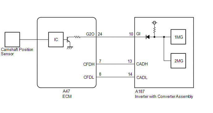
WIRING DIAGRAM
CAUTION / NOTICE / HINT
CAUTION:
Refer to the precautions before inspecting high voltage circuit.
Click here
NOTICE:
- After the ignition switch is turned off, there may be a waiting time before disconnecting the negative (-) auxiliary battery terminal.
Click here
- When disconnecting and reconnecting the auxiliary battery.
HINT:
When disconnecting and reconnecting the auxiliary battery, there is an automatic learning function that completes learning when the respective system is used.
Click here
PROCEDURE
|
1. | CHECK DTC OUTPUT (HEALTH CHECK) |
(a) According to the display on the GTS, select "Health Check".
(b) Check for DTCs.
|
Result | Proceed to |
|---|---|
|
No DTCs are output. |
A |
| DTCs are output. |
B |
(c) Turn the ignition switch off.
| B | .gif) | GO TO DTC CHART |
|
.gif)
|
2. | CHECK CONNECTOR CONNECTION CONDITION (ECM CONNECTOR) |
Click here
OK:
- The connector is connected securely.
- The terminals are not deformed and are connected securely.
- No water or foreign matter in the connector.
|
Result | Proceed to |
|---|---|
|
OK | A |
|
NG (The connector is not connected securely.) |
B |
| NG (The terminals are not making secure contact or are deformed, or water or foreign matter exists in the connector.) |
C |
HINT:
When connecting each connector, connect it with the lock lever raised. Rotate the lock lever downward and make sure that the connector is securely connected. When the lock lever is fully lowered, a click will be heard as its claw engages. After the click is heard, pull up on the connector to confirm that it is securely connected.
| B | | CONNECT SECURELY |
| C | | REPAIR OR REPLACE HARNESS OR CONNECTOR |
|
|
3. | CHECK CONNECTOR CONNECTION CONDITION (INVERTER WITH CONVERTER ASSEMBLY CONNECTOR) |
Click here
OK:
- The connector is connected securely.
- The terminals are not deformed and are connected securely.
- No water or foreign matter in the connector.
|
Result | Proceed to |
|---|---|
|
OK | A |
|
NG (The connector is not connected securely.) |
B |
| NG (The terminals are not making secure contact or are deformed, or water or foreign matter exists in the connector.) |
C |
HINT:
When connecting the connector, connect it with the lock levers raised. Rotate each lock lever downward and make sure that the connector is securely connected. When a lock lever is fully lowered, a click will be heard as its claw engages. After the click is heard, pull up on the connector to confirm that it is securely connected.
| B | | CONNECT SECURELY |
| C | | REPAIR OR REPLACE HARNESS OR CONNECTOR |
|
|
4. | CHECK HARNESS AND CONNECTOR (INVERTER WITH CONVERTER ASSEMBLY - ECM) |
CAUTION:
Be sure to wear insulated gloves.
(a) Check that the service plug grip is not installed.
NOTICE:
After removing the service plug grip, do not turn the ignition switch to ON (READY), unless instructed by the repair manual because this may cause a malfunction.
(b) Disconnect the inverter with converter assembly connector.
(c) Disconnect the ECM connector.
(d) Turn the ignition switch off.
(e) Measure the resistance according to the value(s) in the table below.
Standard Resistance (Check for Open):
|
Tester Connection | Condition |
Specified Condition |
|---|---|---|
|
A187-10 (GI) - A47-24 (G2O) |
Ignition switch off |
Below 1 Ω |
|
A187-13 (CADH) - A47-7 (CFDH) |
Ignition switch off |
Below 1 Ω |
|
A187-14 (CADL) - A47-8 (CFDL) |
Ignition switch off |
Below 1 Ω |
Standard Resistance (Check for Short):
|
Tester Connection | Condition |
Specified Condition |
|---|---|---|
|
A187-10 (GI) or A47-24 (G2O) - Body ground and other terminals |
Ignition switch off |
10 kΩ or higher |
|
A187-13 (CADH) or A47-7 (CFDH) - Body ground and other terminals |
Ignition switch off |
10 kΩ or higher |
|
A187-14 (CADL) or A47-8 (CFDL) - Body ground and other terminals |
Ignition switch off |
10 kΩ or higher |
(f) Reconnect the ECM connector.
(g) Reconnect the inverter with converter assembly connector.
| NG | | REPAIR OR REPLACE HARNESS OR CONNECTOR |
|
|
5. | CHECK INVERTER WITH CONVERTER ASSEMBLY (GI SIGNAL) |
(a) Disconnect the ECM connector.
(b) Turn the ignition switch to ON.
(c) Measure the voltage according to the value(s) in the table below.
Standard Voltage:
|
Tester Connection | Condition |
Specified Condition |
|---|---|---|
|
A47-24 (G2O) - Body ground |
Ignition switch ON |
11 to 14 V |
(d) Turn the ignition switch off.
(e) Reconnect the ECM connector.
| NG | | REPLACE INVERTER WITH CONVERTER ASSEMBLY |
|
|
6. | CHECK INVERTER WITH CONVERTER ASSEMBLY (CAN COMMUNICATION LINE) |
(a) Disconnect the ECM connector.
(b) Measure the resistance according to the value(s) in the table below.
Standard Resistance:
|
Tester Connection | Condition |
Specified Condition |
|---|---|---|
|
A47-7 (CFDH) - A47-8 (CFDL) |
Ignition switch off |
80 to 170 Ω |
(c) Reconnect the ECM connector.
| OK | | REPLACE ECM |
| NG | | REPLACE INVERTER WITH CONVERTER ASSEMBLY |
READ NEXT:
 Camshaft Position Sensor "A" Circuit Bank 1 or Single Sensor Circuit Voltage Below Threshold (P034016,P034017,P034023,P034024)
DESCRIPTION If the cam position signal pulse sent from the ECM via a direct line is abnormal, the motor generator control ECU (MG ECU) (built into the inverter with converter assembly) stores DTC P034
Internal Control Module EEPROM Data Memory Failure (P062F44)
DESCRIPTION The inverter with converter assembly monitors its internal operation and will store this DTC if it detects a malfunction of its EEPROM.
DTC No. Detection Item
DTC Detection
Generator Control Module(EEPROM Learning Value) Calibration / Parameter Memory Failure (P062F46)
DESCRIPTION The inverter with converter assembly monitors its internal operation and will store this DTC if it detects a malfunction of its EEPROM.
DTC No. Detection Item
DTC Detection
SEE MORE:
 Removal
REMOVAL
CAUTION / NOTICE / HINT
COMPONENTS (REMOVAL)
Procedure
Part Name Code
1
INLET NO. 1 AIR CLEANER
17751
-
-
-
2
AIR CLEANER CAP WITH AIR CLEA
ABS Pump Motor Control Internal Electronic Failure (C052C49)
DESCRIPTION
The ABS motor relay and pump motor are built into the brake
actuator assembly.
If the skid control ECU (brake actuator assembly) detects a
malfunction in the drive circuit of the pump motor, this DTC is stored.
DTC No.
Detection Item
DTC Detection
