Toyota Corolla Cross: Brake System (for Hev Model)
Precaution
PRECAUTION
CAUTION:
While the auxiliary battery is connected, even if the ignition switch is off, the brake control system activates when the brake pedal is depressed or the door courtesy switch is turned on. Therefore during servicing of the brake system components, do not depress the brake pedal or open/close the doors while the auxiliary battery is connected.
NOTICE:
- This vehicle is equipped with an SRS (Supplemental Restraint System).
Failure to carry out service operations in the correct sequence could cause
the SRS to unexpectedly deploy during servicing. This may cause a serious
accident. Before servicing (including inspection, replacement, removal,
and installation of parts), be sure to read the precautionary notices for
the Supplemental Restraint System.
Click here
.gif)
- Care must be taken to replace each part properly as it could affect the performance of the brake system and result in a driving hazard. Replace the parts with those having the same part number or equivalent.
- It is very important to keep parts and the area clean when repairing the brake system.
- If the vehicle is equipped with a mobile communication system, refer
to Precaution in the Introduction section.
Click here
- Care must be taken when using magnets as they could affect the performance of the speed sensors.
- Make sure to disable brake control before disconnecting the brake lines.
On-vehicle Inspection
ON-VEHICLE INSPECTION
PROCEDURE
1. INSPECT BRAKE BOOSTER WITH MASTER CYLINDER ASSEMBLY
|
(a) Remove the front disc brake cylinder bleeder plug and set a pedal effort gauge and SST. SST: 09709-29018 09709-00060 |
|
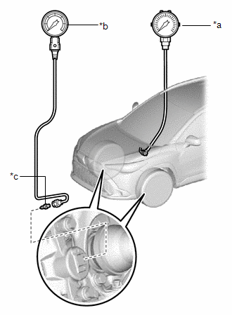
(b) Bleed air from SST (LSPV gauge).
Click here .gif)
(c) Shift lever in P and the parking brake applied.
(d) Turn the ignition switch to ON (READY), check the hydraulic pressure by depressing the brake pedal.
Standard Result:
|
Pedal Effort |
Hydraulic Pressure |
|---|---|
|
50 N (5 kgf, 11.2 lbf) |
2.0 MPa (20.4 kgf/cm2, 290 psi) |
|
100 N (10 kgf, 22.5 lbf) |
5.6 MPa (57.1 kgf/cm2, 812 psi) |
|
150 N (15 kgf, 33.7 lbf) |
7.2 MPa (73.4 kgf/cm2, 1044 psi) |
|
200 N (20 kgf, 45.0 lbf) |
7.6 MPa (77.5 kgf/cm2, 1102 psi) |
(e) Remove the pedal effort gauge and SST, and bleed the brake line.
Click here
(f) If the result is not as specified, replace the brake booster with master cylinder assembly.
Click here

